
Blogs
Base Circle vs Pitch Circle in Gears Explained
Apr
Introduction
Base circle and pitch circle are two gear terms that look easy to mix up, especially because both are theoretical circles and both sit at the center of gear design. On a drawing, they can seem close enough to treat as the same thing. In real engineering work, though, they serve very different purposes.
At Wenlio Gear, this confusion usually shows up when teams move from design language into manufacturing and inspection language. One person is talking about tooth profile generation, another is talking about center distance and ratio, and both think they mean the same “important circle.” This guide explains the difference in a practical way—what each circle does, how they relate, and why using the wrong one can create problems in design, machining, inspection, and assembly.
What these two circles are
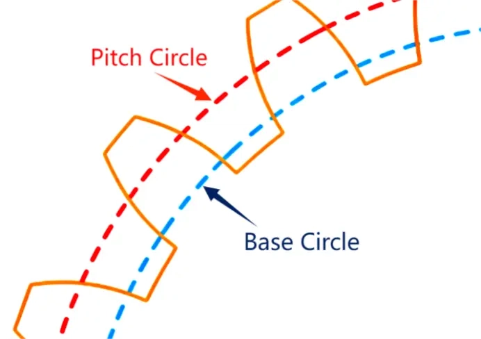
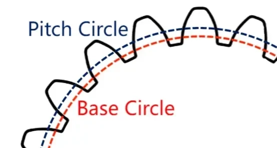
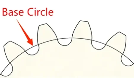
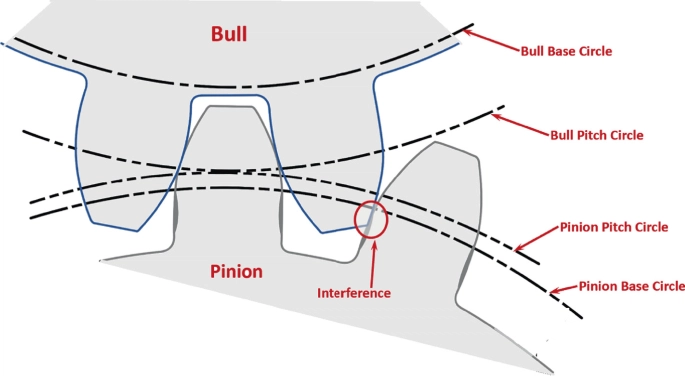
The base circle defines how the involute tooth profile is generated, while the pitch circle is the main reference circle used to define gear size, ratio, and center distance.
Why the difference matters
They belong to different parts of the gear conversation
When engineers talk about involute generation, tooth profile shape, or profile deviation, they are usually working from the base circle. When they talk about module, pitch diameter, center distance, or transmission ratio, they are usually working from the pitch circle.
Using the wrong circle can create practical mistakes
If the base circle and pitch circle are treated as interchangeable, teams can misunderstand what should be inspected, what should be calculated, and which dimensions actually control meshing or assembly. The result may not be an obvious drawing error at first, but it can still lead to poor communication, bad assumptions, and wasted trial-and-error during production.
This matters more on involute gears than people think
In involute systems, the tooth profile is generated from the base circle, but the gear’s main size reference still comes from the pitch circle. That split is exactly why the two terms need to stay separate.
The circles engineers usually talk about around this topic
| Circle | What it is | Main job | Where it matters most |
| Base circle | The theoretical circle that generates the involute profile | Defines tooth profile geometry | Tooth profile design, hobbing/shaping logic, profile inspection |
| Pitch circle | The main design reference circle of a gear | Defines size, ratio, and center distance | Gear design, assembly layout, parameter coordination |
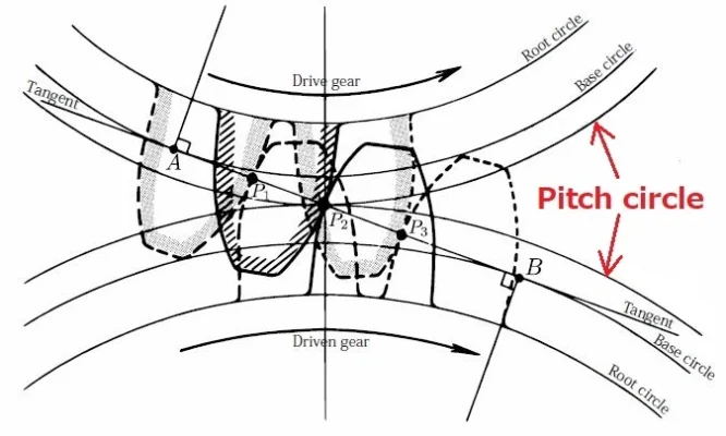
| Working pitch circle | The operating pitch circle of gears in mesh | Reflects actual rolling condition in operation | Transmission analysis, working geometry, assembly deviation study |
A practical reminder: in daily workshop or sourcing language, “pitch circle” may refer either to the design reference circle or to the working pitch circle. That is why clear wording matters in RFQs and technical reviews.
Who needs to understand this difference
- Gear design engineers defining module, tooth count, pressure angle, and involute geometry
- Manufacturing engineers setting hobbing, shaping, grinding, or profile inspection routes
- Quality engineers reviewing profile deviation, runout, and dimensional references
- Assembly and application engineers checking center distance, backlash, and meshing behavior
- Purchasing and project teams reading supplier reports and comparing technical proposals
Even if only one person calculates the geometry, the whole team benefits when the terms stay clear.
How the base circle and pitch circle differ in practice
| Comparison point | Base circle | Pitch circle |
| Core meaning | Starting circle for involute generation | Main reference circle for gear design |
| Main formula link | Derived from pitch circle and pressure angle | Determined from module and tooth count |
| Typical formula | db = d × cos α | d = m × z |
| What it controls | Tooth profile shape | Gear size, ratio, and center distance |
| Use in inspection | Tooth profile analysis and profile deviation checks | Dimensional coordination and reference setup |
| Relation to operation | Indirectly affects meshing through profile shape | Directly tied to basic gear geometry and meshing reference |
This is the simplest way to remember it: the pitch circle tells you how big the gear is supposed to be, while the base circle helps determine what shape the involute tooth profile takes.
What clear understanding improves in real projects
| Project goal | What improves | Why it helps |
| Cleaner design communication | Fewer mixed-up terms in drawings and reviews | Teams calculate and inspect the right thing |
| Better profile control | Clearer link between involute geometry and inspection | Less confusion in tooth profile deviation analysis |
| More stable assembly decisions | Correct use of pitch diameter and center distance | Better meshing coordination in housings |
| Faster troubleshooting | Easier separation of profile issues from setup issues | Reduces guesswork when gears run noisy or hot |
| More consistent supplier communication | RFQs and reports become easier to compare | Less ambiguity in technical discussions |
A simple rule helps here: if the conversation is about shape, think base circle; if it is about size and meshing reference, think pitch circle.
Supplier selection tips when this topic matters
- Be clear about which “pitch circle” you mean. In some discussions, people use pitch circle for both design reference and operating pitch circle. If your project depends on assembly behavior, make the distinction explicit.
- Ask how tooth profile inspection is referenced. If profile deviation is important, confirm whether the supplier is discussing involute generation from the base circle and how that profile is being evaluated.
- Do not separate geometry from assembly conditions. Pitch circle data may define the gear, but working performance still depends on center distance, backlash, housing stiffness, and installation quality.
- Link formulas to deliverables. It is easy to list d = m × z and db = d × cos α in a report. What matters more is whether the supplier can connect those values to profile inspection, assembly datums, and actual meshing behavior.
- Use the same terminology across design, QC, and sourcing. Many avoidable problems come from different teams using the same word for different circles.
Why Choose Us
Wenlio Gear supports precision gear projects with an emphasis on clear technical definitions and inspection language that matches real manufacturing work.
For involute gear programs, we help customers keep design references, profile generation logic, and inspection focus aligned. That means separating base-circle discussions from pitch-circle discussions where needed, so profile control, center-distance planning, and assembly targets are evaluated against the right reference.
We also put value on communication clarity. In practice, that reduces misunderstandings between design, production, and quality teams, especially when a project moves from prototype review into batch production.
FAQ
Q1: Is the base circle the same as the pitch circle?
A: No. The pitch circle is the main design reference circle, while the base circle is the circle used to generate the involute tooth profile.
Q2: Which one is determined first in standard gear design?
A: Usually the pitch circle is determined first from module and tooth count. The base circle is then derived from the pitch circle and the pressure angle.
Q3: Is the base circle always smaller than the pitch circle?
A: In standard involute gears with a normal pressure angle greater than zero, yes. Because db = d × cos α, the base circle diameter is smaller than the pitch circle diameter.
Q4: Which circle matters more for tooth profile inspection?
A: The base circle matters more for involute profile generation and profile inspection logic. The pitch circle matters more for main dimensional definition and meshing reference.
Q5: Why do people confuse these two circles so often?
A: Because both are theoretical circles, both belong to gear geometry, and both are important in design. The names sound similar, but their jobs are different.
10. Conclusion
Gear base circle and pitch circle are closely related, but they are not interchangeable. The pitch circle is the main dimensional reference for gear design and meshing layout, while the base circle is the geometric foundation behind the involute tooth profile. Once that difference is clear, many other gear concepts become easier to understand, including pressure angle, profile inspection, center distance, and meshing behavior.
If you are reviewing a gear drawing, checking involute profile logic, or preparing an RFQ that needs clearer technical language, you are welcome to Contact Us with your drawings and application details so we can help align design references with a practical manufacturing and inspection approach.