
Blogs, Bevel Gear
Bevel Gear—A Guide from a Precision Gear Manufacturer
Nov
1.Introduction
At Wenlio Gear, our focus is simple: precision transmission, proven reliability. We engineer bevel gears for agricultural machinery, heavy truck, construction equipment, EV, and industrial automation. In bevel programs, the combination of tooth geometry, material, heat-treatment, and finishing determines whether a launch runs smoothly and lasts—or slips into rework.
This guide distills the bevel-gear essentials you’ll actually use: types, functions , transmission principles, and the geometry that drives results. It also walks through the manufacturing flow and inspection . If you need a precision gear manufacturer and custom gear supplier to turn drawings into durable bevel gears—read on.

2.Bevel Gears 101 — A Precision Gear Manufacturer’s View
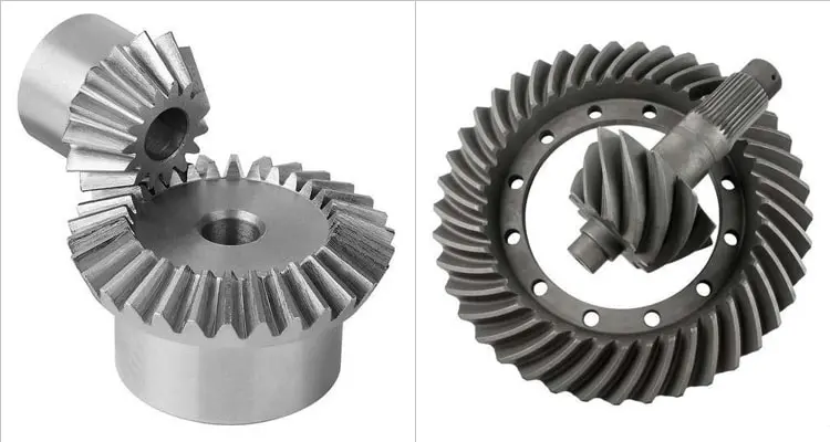
Bevel gears transmit motion and power between intersecting shafts (often at 90°). Teeth are formed on a cone, and the mating crown/pinion pair redirects torque while setting the ratio (which fixes speed and torque change). Choosing the correct bevel pair is about matching duty, envelope, smoothness, and cost—then protecting that choice with a stable manufacturing route.
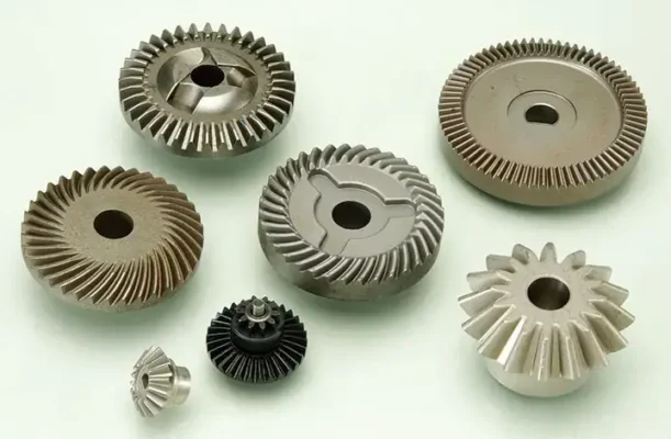
3.Quick type comparison
| Type | Tooth form | Typical load/speed | Advantages | Typical uses |
| Straight Bevel | Tooth lines straight on the cone | Low–moderate duty | Simple, economical, easy to set/inspect | Agricultural implements, transfer cases, moderate-speed axles |
| Spiral Bevel | Curved tooth with progressive contact | Moderate–high duty | Smoother running and higher capacity in the same envelope | EV e-axles, heavy-truck axles, compact industrial gearheads |
Rule of thumb: when the same package must carry more load or run more smoothly, move from straight to spiral and tighten material/heat-treat/finishing control.
4.Functions & Transmission Effects
Change direction: Bevel pairs move power around corners where shafts intersect.
Change speed: Ratio = crown teeth ÷ pinion teeth. A smaller pinion → larger crown yields speed reduction; the reverse yields speed increase.
Change torque: Output torque scales with ratio (minus efficiency losses).
Mesh principle: Conical tooth surfaces roll and slide together; consistent geometry and correct mounting distance keep the contact centered across life.
5.Geometry That Drives Performance
The parameters below determine capacity, smoothness, efficiency, and durability. Designing them once and measuring them every time is how reliable products happen.
| Parameter | What it means | Why it matters | Practical notes |
| Number of teeth | Crown/pinion tooth counts | Sets ratio; more teeth often run more smoothly | Respect minimum pinion teeth to avoid undercut |
| Module / DP | Tooth size (metric/imperial) | Strength & pitch diameter; affects space claim | Choose early with torque and envelope targets |
| Pressure angle (e.g., 20°) | Flank angle vs. radial line | Alters strength and contact; higher angles strengthen teeth | Keep consistent across the pair; confirm load sharing |
| Shaft angle | Angle between axes | Defines geometry family | 90° is common; others are feasible with careful layout |
| Pitch diameter & pitch cone | Rolling references for the mesh | Control kinematics and mounting dimensions | Drive housing design and shim ranges |
| Backlash | Intentional clearance | Prevents binding and supports lubrication | Specify a window; verify before/after heat treat |
| Contact ratio | Avg. teeth in contact | Higher ratios share load and run smoother | Achieve via tooth form and accurate mounting |
| Profile/lead mods | Crowning, tip/root relief | Centers contact and avoids edge loading | Tune with prototype data, then freeze in PPAP |
How we verify at Wenlio Gear: profile/lead/pitch charts, contact-pattern photos at target mounting distance, runout/helix readings, hardness and effective case-depth maps—bundled for PPAP/incoming inspection so your drawing and our parts match.
6.Manufacturing Process Flow
Precision comes from a route that preserves shape, surface, and hardness—not from a single machine. Here’s how we build consistency:
6.1 Machining methods
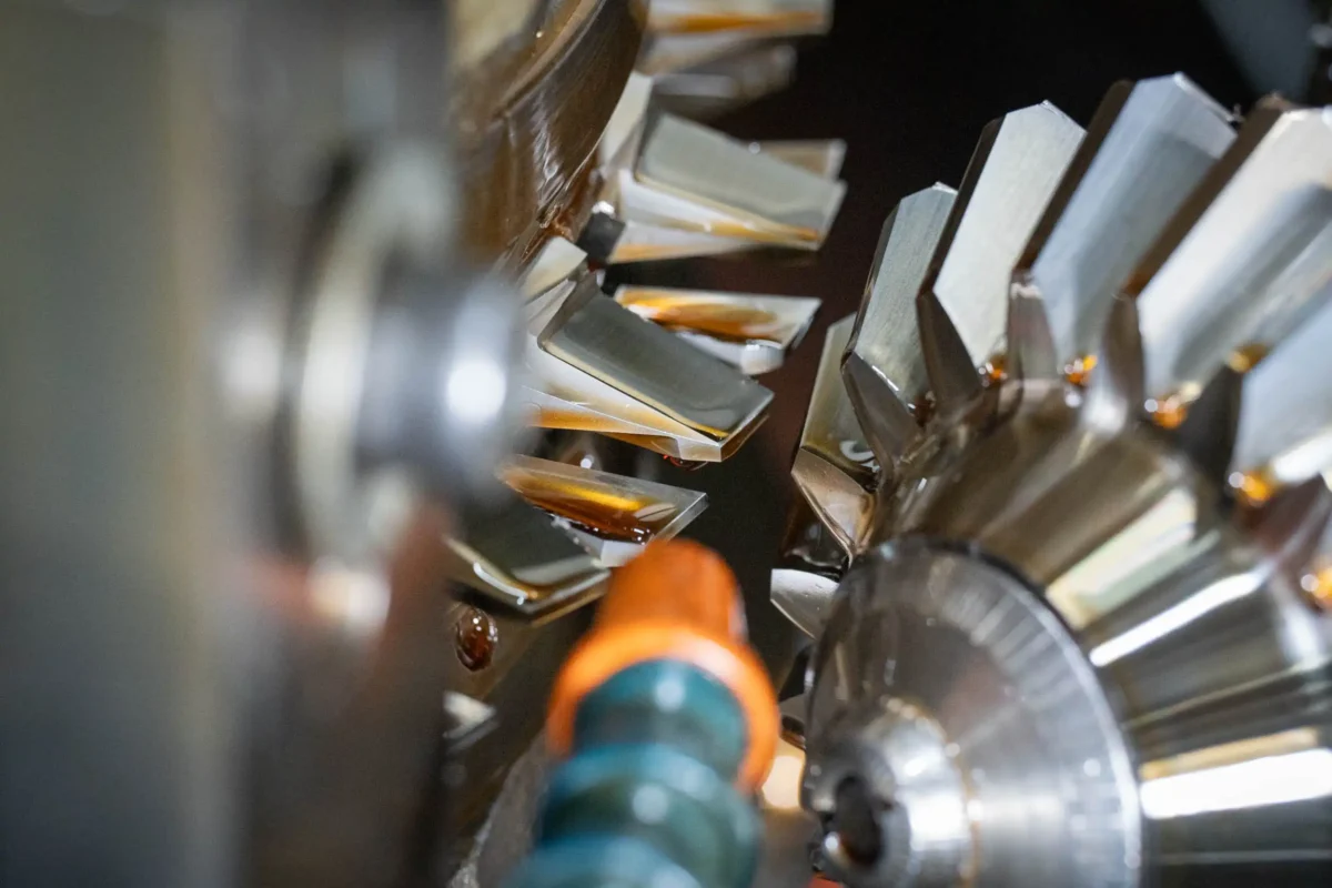
Tooth cutting (CNC): Milling, shaping, or dedicated cutting of the bevel form on prepared blanks. Accurate cutting minimizes deviations that would otherwise raise wear and shorten life.
Finishing after cutting: Lapping and honing improve surface and dimensional accuracy, stabilizing contact and reducing friction prior to heat treat or final grind.
6.2 Heat treatment
Carburizing: Enriches the surface with carbon at high temperature so the case hardens while the core stays tough.
Quenching & tempering: Rapid cool to harden the case, then temper to add toughness and reduce brittleness.
Shot peening: Bombards the surface with small shots to induce compressive stress, improving bending-fatigue resistance in tooth roots.
After heat treat, precision machining: Grind or hone to final dimensions and flank quality within tight tolerances.
6.3 Quality control and inspection
Gear metrology: Coordinate measuring machines and gear testers read tooth profile/lead/pitch; paired with runout/helix data for a complete picture.
Non-destructive testing: Magnetic particle inspection or ultrasound screens surface/subsurface flaws from material or heat treat.
Assembly checks: Light-load roll tests confirm the contact pattern at the specified mounting distance. Where needed, functional runs under load validate smooth transmission and efficiency.

7.Practical Design & Selection — Applying the Concepts
7.1 Ratios, speed, and torque
Speed reduction: A smaller pinion driving a larger crown boosts torque while lowering speed. Check bearing spans and lubrication so the contact stays centered.
Speed increase: A larger pinion driving a smaller crown raises speed; specify tooth strength and surface finish appropriate to higher sliding velocities.
Direction change: Right-angle layouts simplify housings and shorten shafts when space is tight.
Assembly repeatability: Define a consistent mounting distance and shim approach. Confirm with marking compound before locking settings.
7.2 Material & tooth form pairing
Forged case-hardening steels + carburize/quench + grind: maximum life in heavy tractors, trucks, and construction drives.
Vacuum carburizing + gas quench: stable geometry for compact, higher-speed stages (common in e-axle layouts).
Profile/lead crowning with tip relief: keeps contact centered despite deflection under load.
8.Five Sectors We Serve
8.1 Agriculture
Crown-and-pinion sets and transfer stages prioritize long life and field service. Materials and case depth are tuned for dust and shock.
8.2 Heavy Truck
Differential and axle gearing value stable contact over long mileage; consistent heat treat and grinding protect surface integrity.
8.3 Construction Equipment
Right-angle drives must tolerate dust, shocks, and bidirectional duty; robust roots and controlled flank finish are essential.
8.4 EV e-Axles
Bevel stages can unlock packaging in 3-in-1 layouts. Geometry stability at higher shaft speeds reduces friction and wear.
8.5 Industrial Automation
Small bevel stages in gearheads and transfer mechanisms deliver precise positioning without consuming space.
9.What a Custom Gear Supplier Should Promise
When timing is tight, clarity beats slogans. Our standard engagement looks like this:
Drawing review in 1 day, quotation in 2 days
Prototype parts in 15 days, mass production in 30 days
Flexible MOQ — from 1 set (matched pairs available)
Build-to-print or co-design with quick DFM feedback
Evidence with every lot: inspection charts, contact-pattern photos, hardness and case-depth maps
10.Quick Reference Tables
Geometry → outcome map
| Aim | Prioritize | Notes |
| Smooth running | Higher contact ratio; controlled profile/lead | Confirm mounting distance; verify with roll checks |
| Strength in a tight envelope | Module selection; pressure angle; spiral tooth form | Balance tooth thickness vs. interference and housing |
| Consistent field behavior | Backlash window; pitch diameter & cone discipline | Lock shim strategy and measurement plan early |
Process → risk control
| Step | What protects the part | What to avoid |
| Cutting | Rigid setup, correct tools/coatings, chip flow | Excess flank waviness; tool wear left unchecked |
| Heat treat | Documented recipes; target effective case depth | Uncontrolled distortion that shifts mounting settings |
| Finishing | Proper stock split; burn-free grinding windows | Thermal damage that “looks polished” but shortens life |
| Inspection | Charts + contact photos + hardness maps | Pass/fail without evidence for incoming QA |
11.Conclusion
Bevel gears are simple to specify and dependable in service when a precision gear manufacturer and custom gear supplier translate your duty cycle into the right type, ratio, material, heat treat, and finishing plan—and then prove it with inspection evidence. Wenlio Gear focuses on bevel gear where packaging is tight and reliability matters: tractors and harvesters, heavy-truck, construction machinery, EV, and industrial automation. Share your drawing or space claim and we’ll respond with a clear route and a fast plan from prototype to series production. Contact Us.