
Blogs, Bevel Gear
Miter Gear vs Bevel Gear What’s the Difference
Mar
Introduction
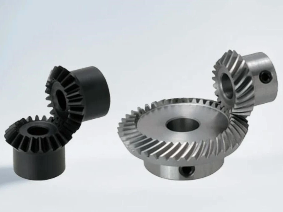
Many engineers know bevel gears. Fewer people use the term “miter gear” daily, so it can create confusion in RFQs and drawings. Some teams treat “miter gear” as a special product line, while others assume it simply means “a bevel gear at 90°.”
In practice, a miter gear is a specific subset of bevel gears with a clear purpose: change direction by 90° without changing speed. This guide explains what miter gears are, how they differ from general bevel gearsets, and what to specify so the gearset behaves correctly in a housing.
The one-sentence definition
A miter gear is a 1:1 bevel gear pair for a 90° shaft angle, while bevel gears cover many ratios, tooth forms, and shaft angles for broader power transmission.
Why the difference matters
Ratio changes the whole design intent
Bevel gearsets can change speed and torque by using different tooth counts. Miter gears keep the ratio fixed at 1:1, so they mainly solve direction change—not speed reduction.
Load and noise expectations are often different
Many miter sets appear in compact tools and instruments where space and simplicity matter. Many bevel sets appear in heavier drivetrains where contact stability, housing stiffness, and durability dominate.
Setup and acceptance evidence must match function
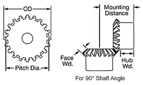
Bevel gearsets are sensitive to mounting distance, backlash, and contact pattern stability. If you don’t define these early, parts may measure “OK” but run noisy or hot after installation.
In short, the word “miter” communicates a fixed design intent (90° and 1:1), while “bevel gear set” leaves room for ratio, tooth form, and packaging choices. If you specify the ratio, shaft angle, and installation targets up front, you reduce the risk of getting parts that fit on paper but drift in contact after assembly.
Quick classification to avoid RFQ confusion
| Term in RFQ | What it means | Ratio | Shaft angle |
| Miter gear set | Bevel gears with equal tooth count | 1:1 | Typically 90° |
| Bevel gear set | Bevel gears with flexible geometry | Variable | Often 90°, can vary |
| Spiral bevel (tooth form) | Curved-tooth bevel set for smoother meshing | Variable | Often 90° |
| Hypoid (offset variant) | Bevel-family set with axis offset | Variable | Near 90° with offset |
Tip: If your requirement is “right angle, same speed,” you’re describing a miter set. If your requirement is “right angle, need reduction,” you’re describing a bevel gearset (not miter).
When you see “spiral bevel” in a quote, it describes the tooth form that usually improves smoothness and load sharing compared with straight teeth. Hypoid sets belong to the same bevel family, but they add an axis offset, which increases sliding. That offset can help packaging, but it also raises lubrication sensitivity—so oil method, temperature limits, and contact verification become more important.
Where they are commonly used
- Hand tools and compact drives (drills, angle heads) needing a 90° direction change
- Automation and instrumentation mechanisms where the ratio stays 1:1
- Small right-angle gearboxes and auxiliary angle drives with limited space
- Drivetrain and industrial right-angle stages that require ratio change, higher load, or long duty cycles
- Repair and rebuild programs that need repeatable fit and predictable backlash/contact behavior
Miter sets often appear in compact right-angle heads where designers want to keep speed the same and minimize parts. In these systems, the housing is usually small, so alignment, bearing fit, and shaft deflection still matter even if the ratio is simple.
General bevel gearsets show up more in drivetrains and industrial right-angle gearboxes because they can provide reduction, higher torque capacity, or longer duty-cycle stability. In those housings, small changes in mounting distance or backlash can shift the contact pattern, so setup discipline becomes part of the product specification, not just assembly work.
The differences that matter in engineering
| Topic | Miter gears | Bevel gearsets (general) |
| Primary purpose | Direction change only (1:1) | Direction change plus ratio change |
| Geometry basics | Equal tooth count; symmetric pitch cone angles (often ~45° each at 90°) | Tooth counts and pitch cone angles vary with ratio |
| Load capability | Depends on size/tooth form; often moderate-duty in compact systems | Can be engineered for heavy duty with tooth form + heat treat + setup control |
| Noise & smoothness | Acceptable for moderate duty; tooth form matters | Spiral bevel can run smoother; straight bevel can be noisier at speed |
| Setup sensitivity | Needs alignment, but less ratio-driven complexity | More sensitive: mounting distance/backlash/contact pattern often decide field performance |
Practical note: “miter” does not automatically mean light duty. A strong miter set is possible, but bevel gearsets offer more flexibility when you must meet torque, life, and NVH targets.
Benefits: which choice fits which goal
| Your goal | Better match | Why |
| Keep speed the same, turn direction 90° | Miter gears | 1:1 intent makes selection and drawing definition simpler |
| Change direction and reduce speed / increase torque | Bevel gearset | Tooth count difference enables ratio |
| Improve smoothness and noise control at speed | Spiral bevel tooth form | Progressive engagement reduces impact |
| Solve packaging with axis offset | Hypoid | Offset layout flexibility (with higher sliding) |
| Make assembly repeatable across batches | Bevel/spiral bevel with setup discipline | Clear datums + backlash + contact control stabilize performance |
If you’re unsure, start by stating the ratio and shaft angle—that alone removes most RFQ ambiguity and helps suppliers propose the right gear family and inspection plan.
For a simple 1:1 direction change, a miter set keeps things clean, but you still need backlash targets, alignment datums, and lubrication assumptions. If you need reduction, higher torque, or tighter NVH, a bevel set—often spiral bevel—offers more tuning room; best results come from aligning geometry with assembly control (mounting distance, contact pattern targets) and measurable inspection evidence.
Supplier selection tips
Before you compare suppliers, make sure everyone is quoting to the same functional target. A short RFQ that includes ratio, shaft angle, duty cycle, and installation targets often produces better results than a long drawing without operating context.
- Write the ratio explicitly (1:1 or not) and confirm the shaft angle (usually 90°).
- Define installation targets, not only gear geometry: mounting distance, backlash window, bearing layout, and housing constraints.
- Align on acceptance evidence: profile/lead/runout (as applicable), plus contact pattern method for bevel/spiral bevel sets under assembly targets.
- Share duty cycle and lubrication reality: speed range, peak torque events, reversals, operating temperature, and lubrication method.
- Confirm material and heat treatment intent: durability targets and how hardness consistency and distortion control are verified.
For the fastest technical alignment, include both the gear drawing and the assembly context (bearing layout, datums, and backlash method). If you require contact pattern evidence, specify the condition (light load or assembly torque) and the acceptance window, so suppliers can plan inspection consistently.
Why Choose Us
Wenlio Gear supports precision transmission components with an emphasis on clear geometry definition and repeatable inspection evidence.
For bevel and miter gear projects, we help teams translate application inputs into manufacturable parameters—especially around functional datums, runout stability, mounting distance, and backlash targets that drive real performance.
We align inspection planning with the gear family, so acceptance evidence reflects how the gearset behaves in a housing rather than only how it measures on a bench. Where appropriate, we support contact-pattern verification methods that match the assembly approach.
FAQ
Q1: Is a miter gear just a bevel gear?
A: Yes. A miter gear is a bevel gear subset designed for 90° transmission with a 1:1 ratio. Engineers use the term “miter” to highlight that fixed ratio and direction-change intent.
Q2: Can a bevel gearset be 1:1 but not called a miter gear?
A: Some teams still call it a bevel set. In practice, “miter” highlights the 1:1, right-angle intent, which can reduce RFQ ambiguity and prevent quoting the wrong ratio.
Q3: Do miter gears always use straight teeth?
A: No. Miter sets can use straight or curved/spiral-like tooth forms depending on noise and load targets. Spiral-like tooth forms often improve smoothness, but they may also raise manufacturing and setup requirements.
Q4: Why do bevel gearsets become noisy after installation changes?
A: Small shifts in mounting distance or backlash can move the contact pattern toward tooth edges, increasing noise and heat. That is why assembly datums and backlash method should be specified, not assumed.
Q5: What should I include in an RFQ?
A: Ratio, shaft angle, duty cycle (speed/torque), mounting distance/backlash targets, lubrication method, space constraints, and required inspection evidence. If the housing is flexible, also note stiffness or deflection concerns to guide pattern targets.
Conclusion
Miter gears and bevel gears belong to the same family, but they serve different engineering goals. Choose miter gears when you need a simple 90° direction change at 1:1. Choose bevel gearsets when you need ratio change, higher load capacity, or tighter control of noise and durability—especially in long duty cycles.
If you are selecting a miter or bevel gearset and want to avoid RFQ ambiguity, you are welcome to Contact Us with your shaft layout, ratio, duty cycle, and installation constraints so we can align the correct gear geometry with a practical inspection and verification plan.
A lot of people mix these two up in practice, especially when just looking at drawings. In real projects, I usually start from the ratio first — if it’s strictly 1:1 and space is limited, miter gears are often enough.
But once load, speed, or noise requirements come in, a standard bevel set gives more flexibility in design and adjustment. The difference becomes more obvious during actual application than in theory.
Good explanation overall, especially for people making early-stage design decisions.