
Blogs
What Is a Miter Gear? 90-degree Bevel Gear Set
Feb
Introduction
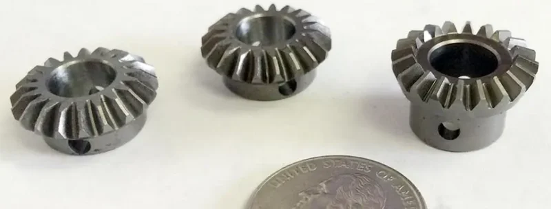
Miter gear sets are bevel gear pairs that transmit motion between intersecting shafts (most often 90 degrees) with a fixed 1:1 ratio—they change direction without changing speed. That sounds straightforward, but “runs well” depends on a small number of practical choices: tooth type, backlash, mounting references, lubrication, and the acceptance criteria used to judge fit and performance.
This article explains miter gears in plain language. You’ll learn what makes a miter set different from a general bevel set, how straight/spiral/Zerol options compare, what key specifications really mean, and how to make confident selection decisions for right-angle drives.
Miter gear basics: the shortest accurate definition
A miter gear set is essentially two matching bevel gears designed for:
Shaft angle: typically 90 degrees
Ratio: 1:1 (same tooth count)
Paired operation: the two gears are intended to run as a matched set
If your application needs a ratio other than 1:1, you are usually specifying a bevel gear set rather than a strict “miter gear set.” In everyday conversation, people sometimes call any right-angle bevel stage a “miter,” so it’s worth stating the ratio explicitly.
Where miter gears are commonly used
Miter gears appear anywhere a compact direction change is needed without changing speed. Typical use cases include:
- Right-angle mechanical drives in industrial equipment
- Motion systems in automation where packaging is tight
- Tooling and machinery sub-assemblies that need a 90-degree turn in power flow
- General mechanical linkages that require equal input/output speed (1:1)
Because these applications often care about noise, temperature rise, and repeatability, selection is less about “any gear that fits” and more about “a gear set that stays stable under load and over time.”
Types of miter gears (and what each is good at)
Most miter gear decisions come down to tooth type. Here are the three practical categories you’ll see most often:
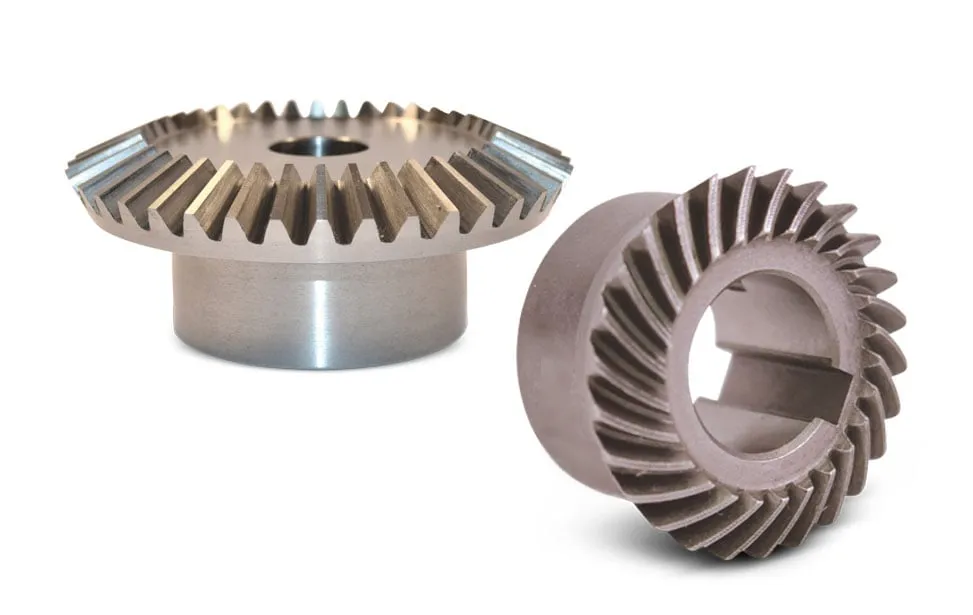
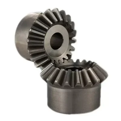
1) Straight miter gears
Straight miter gears have a straight tooth trace.
Why people choose them: simple, cost-effective, widely available
Best for: lower speeds, moderate loads, applications where noise is not the top priority
Typical trade-off: at higher speed, engagement can be more noticeable in sound and vibration, especially if alignment or backlash is not well controlled
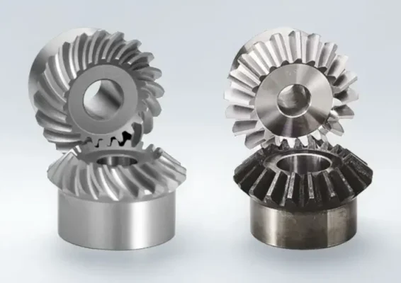
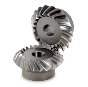
2) Spiral miter gears
Spiral miter gears have a curved tooth trace, which tends to make engagement more progressive.
Why people choose them: smoother feel, typically lower noise, better load sharing
Best for: higher speed, better NVH targets (noise and smoothness), more demanding duty cycles
Typical trade-off: geometry is more complex, and performance is more sensitive to mounting references and correct matching
3) Zerol miter gears (a middle option)
Zerol is often described as a practical compromise between straight and spiral behavior.
Why people choose them: a balance of smoothness and manufacturability
Best for: cases where you want improved running compared to straight teeth, but you don’t want the full complexity of a spiral design
Typical trade-off: still requires proper alignment and contact conditions; the “middle ground” benefit is strongest when the rest of the system is reasonably well controlled
Tip: If your requirement is simply “right-angle, 1:1,” tooth type is the first lever you should decide. It often impacts noise and feel more than small changes in material grade.
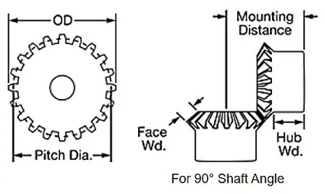
Key features and what to specify
Here’s what matters most when you’re defining or buying a miter gear set.
| Feature | Why it matters | What to specify |
| Shaft angle | Controls geometry and tooth contact | 90 degrees (or exact angle) |
| Tooth type | Major driver of smoothness and noise | straight / spiral / Zerol |
| Module/DP | Tooth size and strength capability | module or diametral pitch |
| Pressure angle | Load capacity & force direction | e.g., 20° (state your spec) |
| Backlash | Heat/noise balance and tolerance stack | target backlash range |
| Mounting references | Shifts contact and load distribution | key mounting dimensions + tolerances |
| Runout & alignment | Affects noise and wear | allowable runout / datum scheme |
| Material & heat treatment | Wear resistance and bending strength | grade + hardness/case targets (if used) |
| Surface condition | Influences friction and lubrication film | roughness target if critical |
| Lubrication method | Sliding contact needs oil film | splash/forced + viscosity window |
Backlash: the simplest spec that people still get wrong
Backlash is the intentional clearance between mating tooth flanks.
Too little backlash can show up as heat, scuffing risk, and sensitivity to temperature expansion.
Too much backlash can show up as impact noise, vibration, and positional looseness.
A good backlash range depends on size, duty, and the stiffness of the supporting structure. The important point is to specify a range and ensure you have a consistent way to check it.
Mounting references: why “same module” doesn’t guarantee the same result
With bevel-type gears, mounting references (the way the gears sit relative to each other) strongly affect tooth contact. Two sets that share module, tooth count, and pressure angle can still behave differently if their mounting assumptions are not the same. This is one reason “drop-in replacement” projects sometimes surprise teams with noise or wear.
Performance trade-offs: noise, efficiency, thrust, and lubrication
Even in a 1:1 right-angle stage, miter gears experience a combination of rolling and sliding at the tooth contact. That makes these factors especially important:
Noise and smoothness
Noise is not just a “gear quality” issue—it’s often a system issue:
- Tooth type (straight vs spiral) affects engagement behavior
- Alignment affects whether contact sits in a stable region of the tooth surface
- Backlash influences impact and sensitivity to stiffness changes
- Housing and shaft stiffness can amplify or damp vibration
If your top priority is quiet running, spiral or well-controlled Zerol options are often preferred, but only when alignment and backlash are also treated as design requirements, not afterthoughts.
Efficiency and heat
Efficiency loss usually appears as temperature rise. Common contributors include:
- Excessive sliding due to contact conditions
- Lubrication film not well matched to speed/load/temperature
- Backlash too tight leading to extra friction
- Misalignment concentrating load and increasing local friction
In practical selection, “efficiency” is not a single number—it’s “stays stable across the real operating window.”
Axial thrust and bearing implications
Bevel-type meshing can generate thrust forces. If the bearings or supports are not sized or arranged to handle these forces, the system may drift in alignment under load—creating a feedback loop of noise and wear. You don’t need to be a bearing specialist to benefit from this insight: if the drive is sensitive, specify the duty and ask the supplier to consider thrust implications.
Lubrication: keep it simple, keep it real
Lubrication needs to provide an oil film under the real temperature range. The most common lubrication mistakes are:
- Choosing viscosity without considering operating temperature
- Assuming “any gear oil” is fine for higher sliding conditions
- Ignoring how oil is delivered (splash vs forced)
If lubrication details are unknown at purchase time, define the expected temperature range and duty. That’s enough to avoid the most costly mismatches early.
Selection checklist
Use this as a decision guide when specifying a miter gear set:
Geometry
- Shaft angle (confirm 90 degrees or specify exact angle)
- Ratio confirmation (1:1)
- Space limits: OD, face width, hub constraints
Duty
- Speed range, torque range, duty cycle
- Shock load (yes/no)
- Noise expectation (quiet / normal / not critical)
Design intent
- Tooth type (straight/spiral/Zerol) aligned to your noise and load targets
- Backlash target range
- Mounting reference assumptions (key distances and datums)
Materials & durability
- Material and heat treatment targets (if required)
- Surface durability target (wear, pitting, scuffing concerns)
Lubrication reality
- Lubrication method and operating temperature window
- Oil viscosity window (if known)
Acceptance
What you will measure and how you will judge success (dimensions, hardness if applicable, backlash, runout, functional feel)
Benefits you can expect when specs are aligned
| Goal | What supports it | What you typically notice |
| Lower noise & smoother feel | appropriate tooth type + stable alignment | less tonal noise, smoother rotation |
| Stable efficiency | correct backlash + oil film + proper contact | lower temperature rise, steady input power |
| Longer service life | adequate strength + surface durability | reduced pitting/scuffing risk |
| Repeatable results | clear mounting & acceptance references | fewer “looks OK but runs poorly” cases |
Common misunderstandings
“Miter gear = any right-angle bevel gear.”
Not always. A strict miter set is 1:1. Always state the ratio.
“If it fits, it will run fine.”
Fit does not guarantee good contact. Backlash and mounting references matter.
“Tighter backlash is always better.”
Too tight can generate heat and accelerate wear. Specify a realistic range.
“Lubrication is a maintenance detail.”
In right-angle bevel contact, lubrication is part of performance design.
Supplier selection tips
Choose a supplier that can clearly explain:
- How they control shaft angle and mounting references(not only tooth size)
- How they set and verify backlashconsistently
- How they match tooth type + lubricationto your duty cycle
- How they ensure pair matchingand repeatability across batches
- How acceptance criteria are documented so your incoming checks are consistent
Why Choose Us
Selection support that stays practical: tooth type, backlash, lubrication, and acceptance alignment
Engineering-first communication: translate your application into measurable specs
Repeatability mindset: focus on what stays stable from prototype to batch
Confidential workflow: drawings and data can be handled under NDA process if needed
FAQ
Q1: Is a miter gear always 90 degrees?
Most commonly yes. If your shaft angle differs, specify the exact angle and confirm the design category.
Q2: Does a miter gear set change speed?
A true miter set is 1:1, so it changes direction without changing speed.
Q3: Are spiral miter gears always quieter?
Often smoother and quieter, but alignment, backlash, lubrication, and housing stiffness still matter.
Q4: What usually causes early noise or wear?
Misalignment and incorrect backlash are common drivers, followed by lubrication mismatch.
Q5: What information is most important for selection?
Shaft angle, 1:1 confirmation, module/DP, tooth type, speed/torque duty, mounting references, and backlash/acceptance targets.
Conclusion
A miter gear is a 90-degree, 1:1 bevel gear set—simple in definition, but performance depends on a short list of controllables: tooth type, backlash, mounting references, lubrication, and acceptance criteria. If you’re planning a right-angle drive stage or replacing an existing set, align those inputs early, then Contact Us to discuss drawings, operating conditions, and inspection expectations (no detailed contact info needed here).