
Blogs
Gear Design Basics Parameters Meshing Strength and Failure
Mar
Introduction
Gear design basics start with one idea: gears sit at the heart of many machines because they deliver accurate speed ratios, compact power transfer, and long service life when designed correctly. However, “gear design” is not only picking a module and tooth count. Real performance depends on involute geometry, meshing conditions, contact ratio, root strength, and how the system handles heat, lubrication, and alignment.
At Wenlio Gear, we often see the same pattern in real projects: a gear looks correct on a drawing, but noise, wear, or early pitting appears because a few basic rules were missed—for example, mismatched pressure angles, insufficient contact ratio, or undercut risk. This guide covers the core gear design knowledge engineers use to keep transmissions reliable, from geometry fundamentals to failure modes and practical checks.
The definition in one sentence
Gear design defines gear geometry and verification rules so a gear pair transmits motion reliably with controlled noise, wear, and durability.
Why the fundamentals matter
Small geometry choices control real behavior
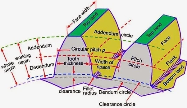
Module, pressure angle, helix angle, and center distance decisions shape contact stress, tooth root strength, and how smoothly the gear pair rolls through mesh. A minor change in geometry can move the contact zone, change backlash sensitivity, and shift the noise signature in a finished assembly.
Many failures start from basic mismatches
Mismatched module or pressure angle prevents correct meshing; insufficient contact ratio increases vibration and load concentration; and undercut weakens the tooth root. When a gear set fails early, the root cause is often visible in the basic parameter definition and tolerance plan.
Good fundamentals reduce iteration and cost
When drawings include clear meshing assumptions, inspection methods, and strength targets, teams spend less time reworking prototypes and more time stabilizing batch production. That clarity also helps purchasing compare suppliers on evidence, not on vague promises.
The topics every gear RFQ should cover
| Topic | What it defines | Why it matters | Typical check |
|---|---|---|---|
| Basic parameters | Module, tooth count, pressure angle, helix angle | Compatibility, size, ratio, and tooth form baseline | Parameter match + drawing review |
| Meshing compatibility | Rules for matching gears | Ensures correct engagement and stable ratio | m and α match; helix direction check |
| Smoothness target | Contact ratio (overlap) | Affects noise, vibration, and load sharing | Contact ratio > 1 |
| Strength baseline | Contact and bending fatigue checks | Prevents pitting and tooth breakage | Surface + root strength verification |
| Reliability risks | Undercut, misalignment sensitivity, lubrication | Prevents early wear and unstable meshing | Undercut risk + tolerance plan |
These five topics cover most “gear design basics” questions in practice. If an RFQ includes them clearly, suppliers can plan tooling, heat treatment, inspection, and acceptance criteria much more reliably.
Who benefits from this knowledge
-
Design engineers defining geometry, center distance, and tolerance stack-up
-
Manufacturing engineers selecting cutting routes and process controls
-
Quality teams verifying tooth thickness/span, runout, and gear accuracy
-
Maintenance and rebuild teams diagnosing wear, noise, and premature failures
-
Sourcing teams writing RFQs and comparing acceptance evidence
Key principles that keep gears working
| Principle | What it means | Why it affects performance |
|---|---|---|
| Gear transmission trade-off | Accurate ratio and high efficiency, but high precision needed | Drives cost expectations and assembly sensitivity |
| Involute behavior | Tooth normal is tangent to the base circle; pressure angle varies with radius | Explains constant ratio and contact conditions |
| Meshing compatibility | Same module and pressure angle; helical angles equal and opposite | Prevents interference, noise, and incorrect engagement |
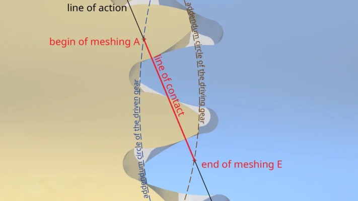
| Continuous transmission | Contact ratio (overlap) must exceed 1 | Avoids intermittent contact and reduces vibration |
| Fundamental law of gearing | Common normal passes through pitch point on line of centers | Keeps velocity ratio constant |
Why involute gears dominate: involute tooth profiles keep a constant velocity ratio even if the center distance changes slightly. This tolerance helps manufacturing and assembly. However, “tolerant” does not mean “immune.” If center distance grows, the operating pressure angle increases, backlash changes, and the contact pattern can shift toward tooth edges.
A practical way to use these principles: first confirm compatibility (module and pressure angle), then ensure continuous contact (contact ratio), then check strength and risks (bending, contact fatigue, undercut, and alignment). This sequence mirrors how most failures develop.
How Gear Design Basics Help Real Projects
| Design goal | What the basics improve | Typical outcome |
|---|---|---|
| Stable motion and ratio | Correct meshing + controlled backlash | Less vibration and more predictable speed control |
| Longer service life | Contact + bending strength checks | Reduced pitting and tooth breakage risk |
| Lower noise risk | Adequate overlap + suitable tooth form | Smoother engagement at speed |
| Robust manufacturing | Clear parameters + inspection alignment | Fewer prototype loops and rework |
| Balanced cost | Avoid over-specifying without need | Better performance-cost trade-off |
A simple rule: most unexpected gear problems trace back to (1) compatibility, (2) contact conditions, or (3) insufficient strength margin. If you confirm those three areas, the gear set becomes far more predictable.
Supplier selection tips
-
Confirm meshing compatibility early: module and pressure angle must match; for helical gears, helix angles must match in magnitude and oppose in direction.
-
Ask how they control undercut and root strength: for low tooth counts, confirm profile shift strategy and how they verify root geometry.
-
Align inspection evidence: decide which checks matter—over pins/span, runout, profile/lead, and (if needed) contact pattern checks.
-
Tie heat treatment and surface condition to duty cycle: confirm hardness targets, case depth needs (if applicable), and how they verify consistency.
-
Request a risk discussion, not just a quote: a good supplier flags load, speed, lubrication, and misalignment sensitivity and suggests practical controls.
If you only request “a gear with module X,” suppliers may quote to geometry only. If you include duty cycle, lubrication assumptions, and failure concerns, they can propose a more reliable manufacturing route and a meaningful inspection plan.
Why Choose Us
Wenlio Gear supports precision gear projects with an emphasis on clear geometry definition and repeatable inspection evidence. We help teams translate design intent into manufacturable parameters and inspection plans, especially around tooth profile consistency, runout stability, and practical strength targets.
We also focus on early alignment of meshing assumptions and quality evidence—so prototype results and batch production results remain comparable, and decisions stay based on measurable criteria rather than guesswork.
FAQ
Q1: Why do most gears use involute tooth profiles?
A: Involute geometry supports a constant velocity ratio and provides tolerance to small center-distance variation, which improves practical manufacturability.
Q2: What must match for two gears to mesh correctly?
A: At minimum: same module and pressure angle. For helical gears: helix angles equal in magnitude and opposite in direction. For bevel gears: compatible cone distance assumptions.
Q3: What does contact ratio greater than 1 mean?
A: It means at least one pair of teeth stays in contact through rotation, improving smoothness and reducing vibration.
Q4: What is root undercut and why does it matter?
A: Undercut removes part of the tooth root involute on low-tooth-count gears, reducing bending strength and overlap. Profile shift often mitigates it.
Q5: What are common gear failure modes?
A: Typical modes include tooth fracture, pitting, scuffing/adhesive wear, and general wear—often driven by load, lubrication, misalignment, or insufficient strength margin.
Conclusion
Gear design basics are not “textbook only.” They decide whether gears run quietly, carry load consistently, and survive the intended duty cycle. When engineers control meshing compatibility, maintain sufficient contact ratio, avoid undercut risk, and verify contact and bending strength, gear systems become far more predictable in both prototype and production.
If you are preparing an RFQ, validating a gear pair, or troubleshooting pitting/noise/wear in a transmission, you are welcome to Contact Us with your drawings and operating conditions so we can align geometry assumptions with a practical manufacturing and inspection plan.