Worm Gears

Worm Gear Drive Manufacturing for Industrial Gearboxes

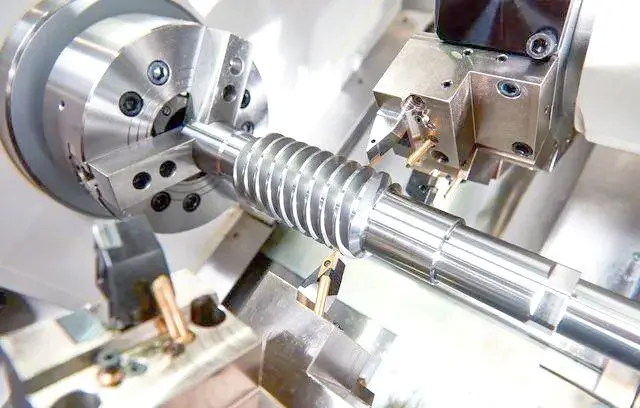
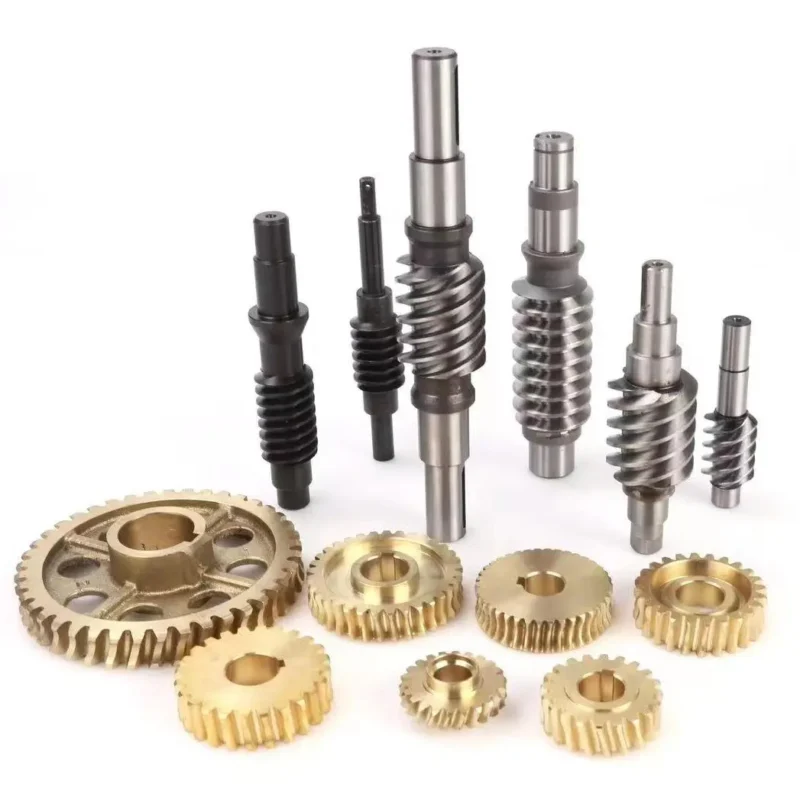
Manufacturing Capabilities: From Machining to Finishing

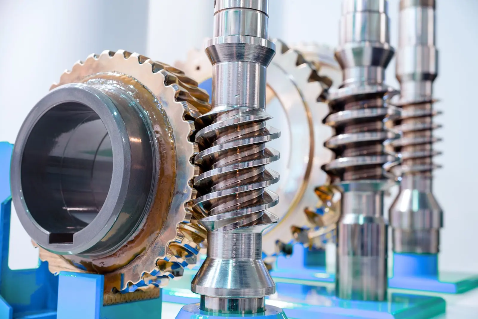
What is a Worm Gear?

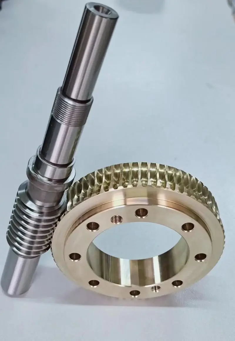
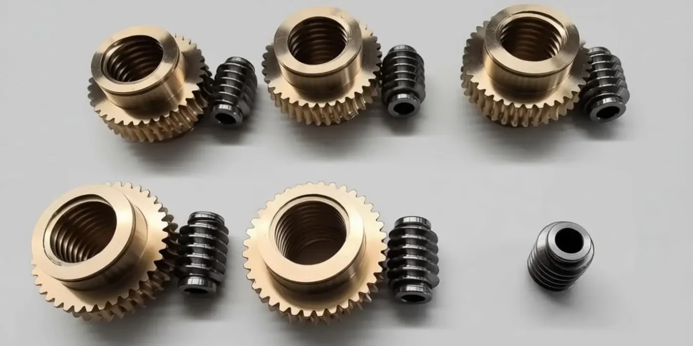
A worm gear consists of a worm (a screw-like gear) that meshes with a worm wheel (a spur gear). It’s used for large speed reductions.

What are the key features and advantages of Worm Gears?

They offer very high reduction ratios in a compact space. They also have a unique locking feature: the worm can easily turn the wheel, but the wheel cannot turn the worm.

What are some common uses and applications for Worm Gears?

They are used in conveyor systems, elevators, and steering systems. Their non-reversible feature makes them ideal for lifting or locking mechanisms.

Worm & Worm Wheel Machining Process

The machining process layout for the worm and worm wheel is arranged according to the drawing requirements. The main process routes are as follows:

(1) Worm (shaft):

Material selection → blank turning → rough turning → finish turning → milling → heat treatment → grinding → gear grinding → inspection.
The detailed operation breakdown is shown in Table 1.

Main Processing of Worm Shaft
Table 1. Worm Machining Process
Worm (Blank material: 40Cr)
Process Operation Machine/Equipment Workplace Fixture Tooling / Cutting Tool Tooling (Aux.)
Turning Rough turning (blank) Conventional lathe Trial Production Center Self-centering chuck Rough turning insert
Center drilling / center hole Trial Production Center Self-centering chuck Center drill
Finish turning Trial Production Center Spring collet (custom-made) CAPTO toolholder + finishing tool + grooving tool (regrind required) Two centers
Double-start thread turning Trial Production Center Custom fixture required Standard threading tool
Milling Milling flats / square Milling machine Trial Production Center
Heat Treatment
Grinding OD grinding Cylindrical grinder Trial Production Center None General-purpose grinding wheel Small center
Tooth Grinding Tooth / thread grinding Thread grinding Wenlio None Thread grinder wheel dresser + form grinding wheel Two centers

(2) Worm wheel:

Material selection → blank turning → rough turning → finish turning → milling → hobbing → milling → inspection.
The detailed operation breakdown is shown in Table 2.

worm gear drive manufacturer
Table 2. Worm Wheel Machining Process
Worm Wheel (Blank material: ZCuSn10Pb1)
Process Operation Machine/Equipment Workplace Fixture Cutting Tool
Turning Rough turning of end face / bore CNC lathe Trial Production Center Self-centering chuck Rough turning insert
Finish turning of end face / bore CNC lathe Trial Production Center Self-centering chuck Finishing insert
Drilling Drilling Drill press Trial Production Center Custom positioning fixture required General-purpose drill bit
Turning Rough / finish OD turning CNC lathe Trial Production Center Custom centering adapter plate required Finishing insert
Milling Slot milling (keyway/slot) Conventional rough milling machine Trial Production Center Custom positioning fixture required Standard slotting cutter
Hobbing Gear hobbing Gleason gear hobbing machine Trial Production Center Hobbing fixture Hob cutter (design & purchase required)
Milling Remove excess material CNC milling machine Trial Production Center Custom positioning fixture required Milling cutter

Main Machining Process of the Worm

(1) Material selection

Worms are generally made of alloy steel (e.g., 16MnCr5, 20CrMnTi, 20Cr, 40Cr, 42CrMo) or carbon steel (e.g., 40Cr). In most cases, the tooth surface is heat-treated (e.g., carburizing and quenching) to obtain higher hardness, followed by grinding. For example, material 40Cr, 16MnCr5, 20CrMnTi, with a tooth-surface hardness of 45–55 HRC after hardening.

(2) Turning the tooth profile

A CNC lathe is used. Standard inserts must be re-ground to form the required tool geometry. Since the tooth groove profile on the normal section is a straight-sided profile, and the tooth thickness at the pitch-circle height equals the tooth-space clearance—both being 0.5Px —the turning tool is dressed to the dimensions. During turning, the tool is aligned with the normal-plane centerline of the tooth groove to generate the profile.

In machining, one helix is produced first. As the dimension approaches the target, a certain allowance is left. The tool is then set on the opposite flank of the same thread to machine the second helix to size.

(3) Grinding

The tooth-profile accuracy of the worm largely depends on the dressing accuracy of the grinding-wheel profile. To obtain an approximately correct wheel profile, a diamond dresser is used to dress the wheel, cutting along the axial direction. During grinding, the workpiece is mounted between centers and aligned. After grinding, inspection can be performed.

Made to Drawing Worm Gear

Custom support: drawing review, key parameter checklist, fast quotation.

Main Machining Operations of the Worm Wheel

worm wheel gear machining

OEM Worm Gear Set

Material + heat treatment options per drawing/spec, with traceable QC records.

(1) Material selection

Worm wheels are typically made of tin bronze (e.g., ZCuSn10P1, ZCuAl10Fe3, HT150, HT200, CuSn12Ni2-C-GZ, CuSn12Ni2-C-GC, CuZn37Mn3Al2Si-R510), which provides good conformability and load-carrying performance. After running-in with a steel worm, the mating contact surfaces fit each other better, increasing the effective bearing area.

(2) Hobbing

A locating mandrel fixture is used to position the worm wheel center, and a special worm-wheel hob is used for hobbing. Before hobbing, the hob axis must be aligned, and the center distance from the hob center to the workpiece center must be adjusted. During cutting, the hob performs pure radial cutting, with a radial feed of 0.03–0.05 mm/rev.
The hob feeds radially into the worm wheel from the tooth tip gradually to the full tooth depth. This method offers short machining time and high productivity. The inspection results of the worm wheel are shown.

RUSH-READY CUSTOM GEARS—SLAS AVAILABLE

72-HOUR QUOTES. ACCELERATED PRODUCTION WINDOWS.

Custom Worm Gear & Worm Wheel Sets

Custom Worm Gear & Worm Wheel Sets — Stable Quality, On-Time Delivery

Wenlio Gear provides a full range of manufacturing services for gears, gear components, and assemblies. With skilled technicians, proven know-how, and a fully equipped facility, we deliver precise, custom work for your gear projects.


SLA Packages (Lead Time & Pricing)

Tier Lead Time Price Uplift
Standard 40–45 days Base price (0%)
Expedited 25–30 days +12–18%
Rush 10–15 days +25–40%
Note: Values are illustrative. Calibrate using Wenlio Gear’s actual capacity and historical data (material categories, size limits, heat-treat capability, yield).

FAQ

Q1. What accuracy grade can you achieve for worm gears?

We manufacture to the accuracy and inspection standard specified on your drawing (e.g., ANSI/AGMA 2011-B14 for unassembled cylindrical wormgearing when required).

Q2. How do you define and control backlash?

Backlash is mainly affected by tooth thickness and the operating center distance; we confirm your target backlash at the working center distance and control it through machining allowances and inspection.

Q3. What affects worm gear efficiency?

Worm drives are dominated by sliding friction, so efficiency depends on factors such as lead angle, sliding speed, lubricant, surface quality, and installation conditions.

Q4. How can noise be reduced in a worm gear set?

Noise is influenced by backlash/alignment, contact pattern, surface finish, and lubrication; we help optimize these based on your speed/load and duty cycle.

Q5. What information do you need for an RFQ?

Please share drawing/3D, ratio & center distance, starts/teeth, module/DP, hand, face width, materials/heat treatment, speed/load, lubrication, and target accuracy/backlash requirements.

Q6. What materials are commonly used for worm and wheel?

A common combination is a hardened steel worm with a bronze wheel, offering good strength and lubricity for sliding contact.

REQUEST A QUOTE

To request a quote, please send email to sales@wenlio.com. If you have a more urgent request, please call us at +86 18257981010 for immediate assistance.