
Blogs, Bevel Gear
Spiral Bevel Gear Angles and What They Mean
Apr
Introduction
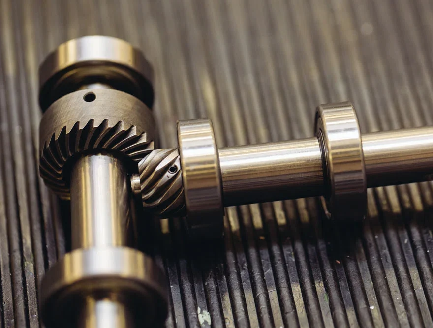
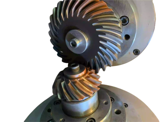
Spiral bevel gears are used when a drive needs to turn power smoothly through an angle, usually in a compact space. You will find them in axle drives, agricultural machines, construction equipment, electric vehicle reducers, and many other right-angle transmission systems. On a drawing, the gear may look straightforward. In real projects, though, a spiral bevel gear set depends heavily on a few key angles.
At Wenlio Gear, these angles usually come up at two moments: early in design, and later when a customer is trying to understand noise, unstable contact, or uneven wear. A gear can look correct in size and still perform poorly if the angle relationships do not match the real duty cycle and assembly condition. This article explains the main angles in spiral bevel gears and what they actually mean in practical engineering terms.
What spiral bevel gear angles are
Spiral bevel gear angles are the geometric angles that define tooth direction, force flow, shaft layout, and meshing behavior in a spiral bevel gear set.
Why these angles matter
They influence how the tooth surfaces carry load.
In spiral bevel gears, tooth contact depends on more than tooth count and size. The main angles affect where contact starts, how it spreads across the flank, and how sensitive the gear pair is to setup variation.
They affect noise, heat, and durability.
A gear set can still assemble even when the angle combination is not ideal, but it may run louder, create more sliding loss, or show unstable contact under load. That is why these angles should be treated as performance parameters, not just drawing data.
They matter in production as much as in design.
Angle choices influence machining, heat-treatment response, setup targets, and inspection focus. If the design angle strategy and manufacturing strategy do not match, good results become difficult to repeat from prototype to batch production.
The main angles engineers usually discuss
| Angle | What it describes | Why it matters |
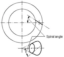
| Spiral angle | The direction and inclination of the tooth trace | Affects smoothness, load sharing, and noise |
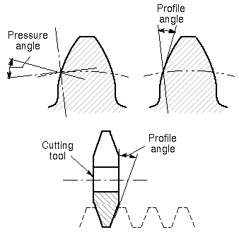
| Pressure angle | The angle that influences how force is transmitted through the tooth contact | Affects strength, bearing load, and running behavior |
| Shaft angle | The included angle between the two gear axes | Defines gearbox layout and working arrangement |
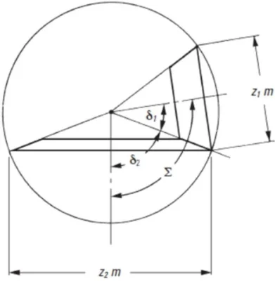
| Pitch cone angle | The cone geometry of each gear in the pair | Affects gear shape, ratio relationship, and contact position |
These angles do not work alone. Once one changes, the rest often need to be reviewed as part of the same gearset.
Where these angles matter most
- Agricultural machinery bevel gearboxes
- Heavy-duty truck driveline and axle systems
- Construction equipment transmission stages
- Electric vehicle angle-drive reducers
- Industrial automation and compact right-angle drives
In each of these applications, spiral bevel gears are expected to do more than fit. They are expected to run smoothly, carry load reliably, and stay stable through real operating conditions. That is why angle definition matters so much.
What each angle really changes in practice
Spiral angle
The spiral angle defines how the tooth line curves across the gear face. Compared with straight bevel gears, spiral bevel gears engage more gradually, which usually improves smoothness and helps spread the load across the tooth surface.
In real applications, a larger spiral angle often helps reduce noise and improve load sharing, but it also increases manufacturing complexity and can make setup more demanding. A smaller spiral angle may be easier to produce, but it does not always deliver the same refinement under speed and load.
Pressure angle
The pressure angle affects how the tooth force is distributed. Part of the force transmits torque, while another part loads the bearings and housing. A larger pressure angle often improves strength and load capacity, but it may also increase bearing load and reduce smoothness. A smaller pressure angle can help running stability and reduce some side effects, but it may lower load capacity.
That is why pressure angle should be chosen around the application target, not by rule of thumb alone.
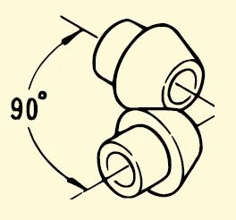
Shaft angle
The shaft angle defines the layout of the two intersecting shafts. In many spiral bevel applications, this angle is 90 degrees, but it does not have to be. Once the shaft angle changes, the whole gear pair geometry changes with it. That affects packaging, meshing position, and manufacturing difficulty.
From a system point of view, shaft angle is often one of the first design inputs because it is tied directly to gearbox layout.
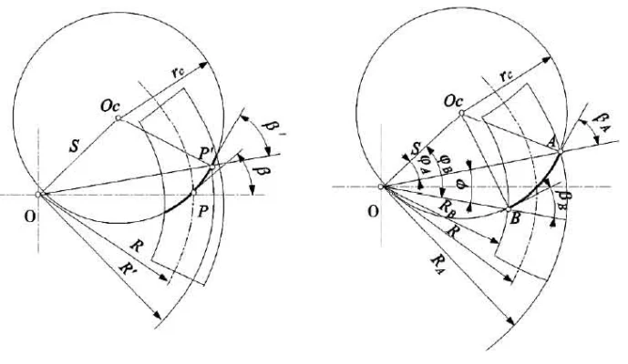
Pitch cone angle
The pitch cone angle controls the conical working geometry of each member in the pair. It is closely related to ratio and shaft layout, and it strongly affects the final gear shape, tooth length distribution, and contact zone position.
If the pitch cone angle is not right, the gear may still look close to nominal size, but the meshing behavior will not match the design intent.
What good angle design improves
| Design goal | What improves | Why it helps |
| Smoother running | Better contact progression | Lower impact and lower noise |
| Higher load capacity | Better force distribution | More stable flank loading |
| Better assembly consistency | Clearer setup targets | Less contact-pattern drift in production |
| More reliable field performance | Angles match real duty cycle | Lower risk of wear, heat, and noise complaints |
| Easier verification | Angles support practical inspection logic | Better link between design and QC |
A useful way to look at spiral bevel gear angles is this: they do not just define shape, they define behavior.
Supplier selection tips
- Do not ask for angle values without application context. Spiral angle, pressure angle, shaft angle, and pitch cone angle only make sense when tied to ratio, duty cycle, packaging, and lubrication.
- Ask how the supplier controls real contact, not only nominal geometry. A spiral bevel project is not complete when the angle values are listed. The supplier should also explain how those values translate into usable contact behavior after machining and heat treatment.
- Make sure setup logic and inspection logic match. It is not enough to show correct numbers on a drawing. The supplier should be able to connect those numbers to mounting distance, backlash, and contact checks.
- Check manufacturability and repeatability. Some angle combinations may look attractive on paper but become difficult to hold consistently in batch production.
- Review the gearset as a pair. Spiral bevel gears work together as a matched set. Angle decisions should be reviewed at pair level, not one member at a time.
Why Choose Us
Wenlio Gear supports precision spiral bevel gear projects with a focus on geometry clarity, real contact behavior, and repeatable inspection evidence.
For spiral bevel applications, we help teams connect angle selection with actual operating needs, including noise targets, load requirements, shaft layout, and assembly limits. That means the project is evaluated not only by nominal dimensions, but by whether the gear set can achieve stable meshing in the final application.
We also pay close attention to the link between design, manufacturability, and verification. In practice, that helps reduce the gap between a good drawing and a gear set that performs well in service.
FAQ
Q1: Which angle matters most in a spiral bevel gear?
A: There is no single answer. Spiral angle, pressure angle, shaft angle, and pitch cone angle work together. The most important one depends on whether the priority is load, packaging, noise, or manufacturability.
Q2: Does a larger spiral angle always mean better performance?
A: Not always. A larger spiral angle can improve smoothness and load sharing, but it also makes processing and setup more demanding.
Q3: Why can two spiral bevel gear sets with the same ratio behave differently?
A: Because ratio alone does not define the gearset. Angle selection, tooth form, setup, and contact control all change how the gears actually run.
Q4: Is the shaft angle always 90 degrees?
A: No. Ninety degrees is common, but spiral bevel gears can also be designed for other shaft angles when the application layout requires it.
Q5: What should I include in an RFQ for a spiral bevel gear project?
A: Include ratio, shaft angle, duty cycle, noise expectations, packaging limits, lubrication conditions, and any assembly targets such as backlash or mounting distance.
Conclusion
Spiral bevel gear angles are not just theoretical design terms. They directly affect how the gear set carries load, how quietly it runs, how sensitive it is to setup variation, and how reliable it will be in real service. Once these angles are chosen with the application in mind, the gear set becomes much easier to manufacture, inspect, and assemble with confidence.
If you are developing a spiral bevel gear project or reviewing an existing gear set, you are welcome to Contact Us with your drawings and operating conditions so we can help align the angle design with a practical manufacturing and inspection plan.