
Blogs, Bevel Gear, Helical Gear
Helical vs Spiral Gears Differences and Applications
Mar
Introduction
Helical vs spiral gears is a common comparison in drivetrain discussions, but the term “spiral gear” can mean different things in practice. In many right-angle applications, buyers use “spiral gear” to mean a spiral bevel gear set. In other contexts, it may refer to crossed helical (skew) gears.
At Wenlio Gear, we see this confusion in RFQs and troubleshooting: a drawing looks correct, but the gearbox runs noisy or hot because the chosen gear family does not match the shaft layout and duty cycle. This guide clarifies the terminology first, then compares how each option behaves in efficiency, noise, lubrication, and inspection planning—so you can choose the right gearset with fewer iterations.
The one-sentence definition
Helical gears are cylindrical gears mainly for parallel shafts, while “spiral gears” most often means spiral bevel gears for intersecting shafts (and sometimes means crossed helical gears for skew shafts).
Why the wording matters
Because shaft layout decides the gear family
Parallel shafts usually point to helical gears. Intersecting shafts (often 90°) point to bevel gearsets—commonly spiral bevel for smoother operation. Skew shafts (neither parallel nor intersecting) may point to crossed helical gears when load requirements allow.
Because the trade-offs are not the same
Helical gears typically deliver high efficiency and smooth running on parallel shafts but generate axial thrust. Spiral bevel gears can deliver smooth right-angle power transfer, but they rely on correct mounting distance, backlash, and contact pattern control. Crossed helical gears can solve compact skew layouts, yet they often carry less load and run with more sliding loss.
Because acceptance evidence must match function
Cylindrical gears often use profile/lead/pitch and runout evidence. Spiral bevel projects often need assembly-oriented checks such as contact pattern and backlash under functional datums. Clear evidence criteria prevents “pass on paper, fail in housing.”
What people usually mean by “spiral gears”
| What “spiral gear” means | Shaft relationship | Best fit | Common limitation |
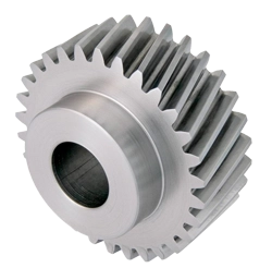
| Helical gear (baseline) | Parallel shafts | Gearboxes needing smooth, efficient power transfer | Axial thrust; alignment and bearing support matter |
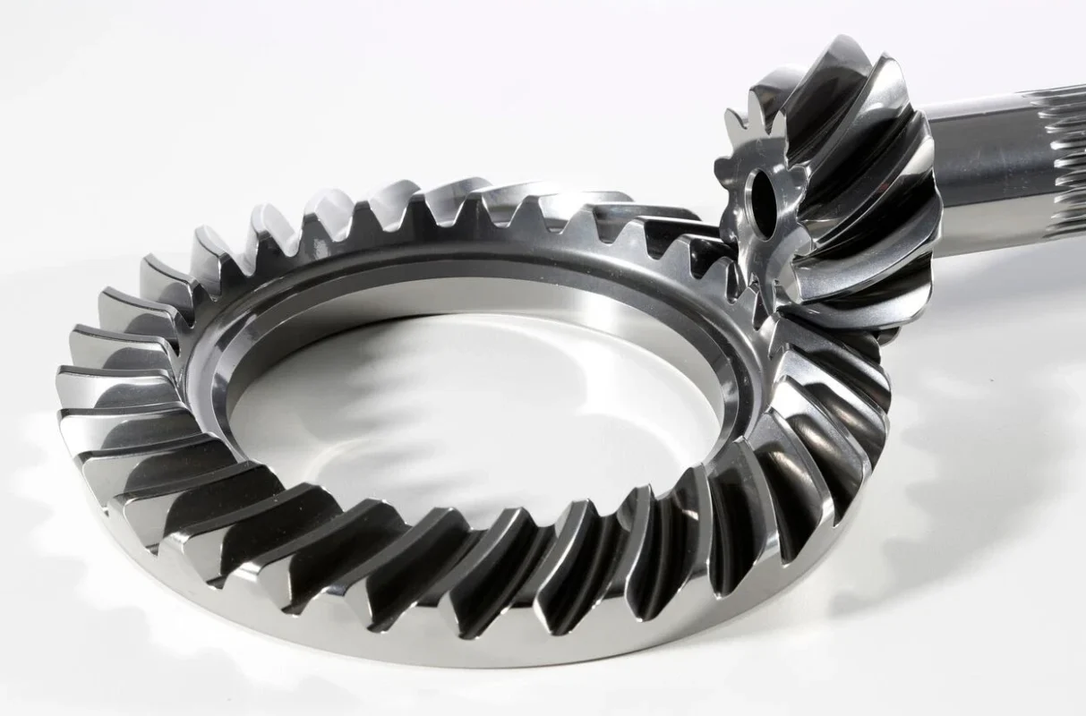
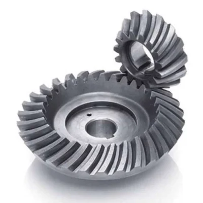
| Spiral bevel gear set (most common meaning) | Intersecting shafts (often 90°) | Right-angle drives with good NVH and load sharing | Setup-sensitive: mounting distance/backlash and contact pattern |
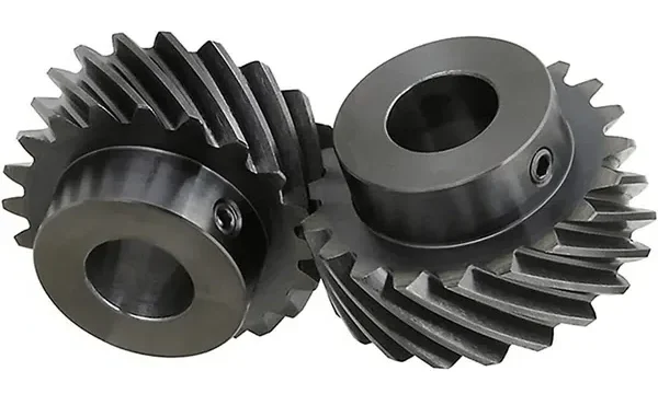
| Crossed helical / skew gears (alternate meaning) | Skew shafts (non-parallel, non-intersecting) | Compact angle stages at light-to-moderate load | Lower efficiency/load capacity; wear sensitivity |
Practical tip: if your application is a right-angle gearbox in a housing (axle, differential-style stage, PTO gearbox), “spiral gear” almost always means spiral bevel gears. If shafts are skewed and the load is light, crossed helical may appear instead.
Typical users and applications
- Parallel-axis gearboxes in industrial equipment and automation (helical)
- Right-angle drivetrains and gearboxes (spiral bevel)
- Compact skew-shaft angle drives where packaging dominates (crossed helical)
- Noise-sensitive transmissions where contact stability matters (helical / spiral bevel)
- Repair and rebuild programs that need repeatable fit, backlash control, and predictable wear behavior
The differences that affect performance
| Topic | Helical gears | Spiral bevel gears | Crossed helical (skew) gears |
| Shaft layout | Parallel | Intersecting (often 90°) | Skew shafts |
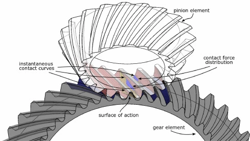
| Contact behavior | Progressive contact; good overlap | Progressive surface contact; stable when set correctly | More sliding; smaller effective contact |
| Efficiency & heat | Generally high; manageable heat | High when set correctly; depends on load/setup | Often lower; heat/wear sensitivity rises |
| Noise behavior | Quiet vs spur; good at speed | Smooth vs straight bevel; NVH depends on contact pattern | Can be smooth at light load; wear can increase noise |
| Main setup risk | Axial thrust + alignment | Mounting distance/backlash + pattern stability | Wear/scuffing risk; limited capacity |
| Inspection focus | Profile/lead/pitch, runout, tooth thickness evidence | Contact pattern, backlash targets, runout tied to assembly datums | Wear control, surface condition, fit and alignment |
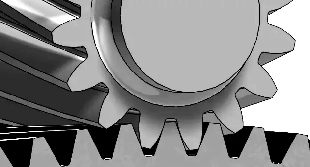
Behind these differences sits the contact physics. Helical gears and spiral bevel gears rely on progressive engagement that distributes load across multiple teeth, which helps smoothness. Crossed helical gears often introduce more sliding, so lubrication quality and surface condition become more sensitive.
Also note that both helical and spiral bevel geometries generate axial components of force. That does not make them “bad,” but it does mean bearing support, housing stiffness, and alignment control play a bigger role in real performance than the gear drawing alone.
Benefits matched to your design goal
| Your goal | Best match | Why |
| Efficient, quiet parallel-axis transmission | Helical gears | High efficiency and mature inspection methods for repeatability |
| Smooth right-angle power transfer | Spiral bevel gears | Designed for intersecting shafts with stable contact when set correctly |
| Skew-shaft packaging with minimal parts | Crossed helical gears (if load allows) | Enables skew layouts without bevel geometry |
| High-speed stability and NVH control | Helical / spiral bevel | Progressive engagement reduces impact and vibration |
| Repeatable assembly behavior | Helical / spiral bevel (with setup discipline) | Clear datums + correct evidence improves consistency |
Shortcut selection: parallel shafts → helical; intersecting shafts → spiral bevel; skew shafts → crossed helical if the duty cycle is light enough. When in doubt, start from the shaft layout and the duty cycle, then refine by noise, thermal limits, and available installation space.
Supplier selection tips
- State the shaft relationship clearly (parallel / intersecting angle / skew) and include any packaging constraints.
- Provide duty-cycle inputs, not only nominal torque: speed range, peak torque events, reversals, and temperature limits.
- For spiral bevel projects, share mounting distance and backlash targets, bearing layout, and how the housing defines functional datums.
- Align inspection evidence to the gear family: helical—profile/lead/pitch/runout; spiral bevel—contact pattern + backlash under assembly targets.
- Confirm lubrication method and contamination expectations, especially for crossed helical and high-sliding conditions.
Why Choose Us
Wenlio Gear supports precision transmission projects with an emphasis on clear geometry definition and repeatable inspection evidence.
For helical gear programs, we align profile/lead targets, runout control, and measurable acceptance evidence so prototypes and batches remain comparable.
For spiral bevel projects, we focus on the factors that decide real housing performance—mounting distance, backlash window, contact pattern stability, and runout tied to functional datums.
We also help teams clarify terminology early (helical vs spiral bevel vs crossed helical) and translate application inputs into a practical manufacturing and verification plan.
FAQ
Q1: Are spiral gears the same as spiral bevel gears?
A: Not always. Many buyers use “spiral gears” to mean spiral bevel gears, but some texts use it for crossed helical (skew) gears. Always confirm shaft layout.
Q2: Which is more efficient, helical or spiral bevel?
A: Both can be highly efficient in their intended layouts. Helical gears often run very efficiently on parallel shafts. Spiral bevel efficiency depends on setup, load, and lubrication.
Q3: Why do spiral bevel gears get noisy after installation changes?
A: Small shifts in mounting distance or backlash can move the contact pattern toward tooth edges, increasing noise and heat.
Q4: When should I consider crossed helical gears?
A: When shafts are skewed and the load is light-to-moderate, and packaging matters more than maximum efficiency or heavy-duty life.
Q5: What should I include in an RFQ to avoid wrong quotes?
A: Shaft relationship, ratio, speed/torque range, duty cycle, lubrication method, installation targets (backlash/mounting distance), and required inspection evidence.
Conclusion
Helical and spiral gears can both deliver smooth motion, but they serve different shaft layouts and engineering priorities. Helical gears usually fit parallel-axis transmissions where efficiency and load sharing matter. Spiral bevel gears usually fit intersecting-axis right-angle drives where performance depends on correct mounting distance, backlash, and contact stability. Crossed helical gears may fit skew-shaft layouts when load demands allow.
If you are selecting a gearset and want to avoid terminology mix-ups, you are welcome to Contact Us with your shaft layout, target ratio, duty cycle, and installation constraints so we can help align the correct gear family with a practical verification plan.
Good read. The biggest problem with “helical vs spiral” is that people are not always using the word “spiral” the same way. Once you separate shaft layout from gear naming, the comparison becomes much more practical.