
Blogs, Pinion Gear
Ring and Pinion Gear Faults and Selection Guide
May
Introduction
In many driveline systems, the ring and pinion set is the stage that makes the whole layout practical. It turns power through 90 degrees, reduces speed, increases torque, and sends that torque where the machine actually needs it. In a vehicle, that usually means the axle. In machinery, it may mean the final drive, a compact reduction stage, or a right-angle transmission point. The source text also frames ring and pinion as a bevel-gear-based assembly used for 90-degree direction change plus speed reduction and torque increase, especially in vehicles and heavy equipment.
At Wenlio gear, this topic fits naturally into the broader bevel gear conversation. Buyers often know they need a “ring and pinion,” but the real questions usually come later: Should the set be spiral bevel or hypoid? What ratio should be selected? Why does one set run quietly while another develops whine, heat, or early tooth damage? Those questions matter much more than the name alone. This guide explains ring and pinion gears in a practical way, focusing on how they work, where they are used, what usually goes wrong, and what should be clarified before sourcing.
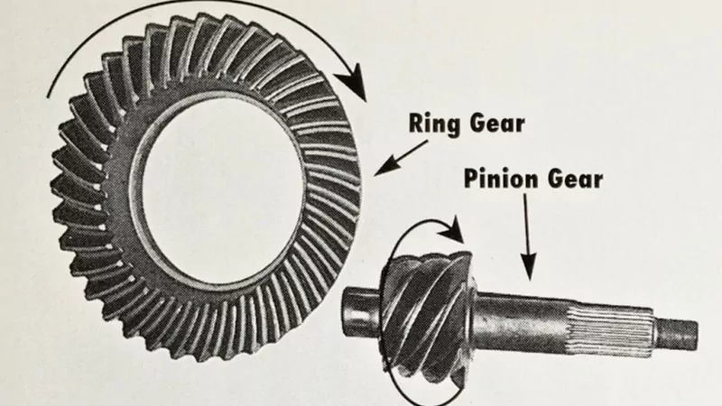
What a ring and pinion gear is
A ring and pinion gear set is a matched final-drive gear pair, usually based on bevel-gear geometry, that changes power direction by about 90 degrees while reducing speed and increasing torque.
Why this gear set matters
It is often the last major torque-conversion stage before the load.
In a driveline, the ring and pinion set usually sits close to the wheels, axle output, or final reduction point. That means it does not just transmit power. It shapes how the whole system feels in service—pulling force, noise, smoothness, and temperature behavior.
It turns ratio choice into real machine behavior.
A small change in ratio may alter climbing ability, low-speed pulling force, road speed, or operating efficiency. That is why ring and pinion selection is rarely just a geometry exercise. It is a system decision.
It is one of the easiest places for field problems to show up.
If setup, lubrication, tooth contact, or bearing condition is wrong, the ring and pinion set often tells you quickly. Noise, heat, pitting, scuffing, and backlash changes tend to show up here earlier than many buyers expect. The source material highlights the same pattern by focusing on pitting, scuffing, noise, leakage, wear, and tooth breakage as the most common failures.
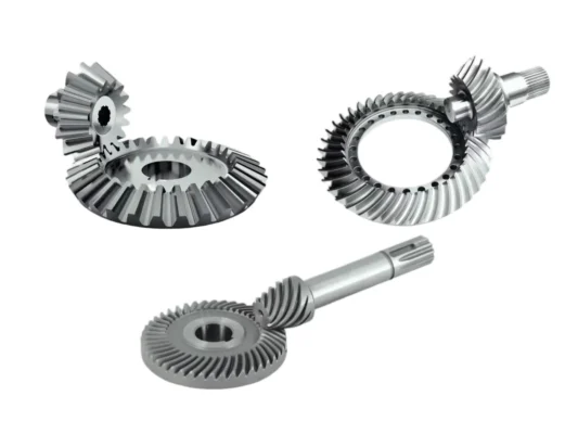
The ring and pinion types buyers most often compare
| Type | Typical shaft relationship | Best fit | Main note |
|---|---|---|---|
| Straight bevel ring and pinion | Intersecting shafts | Simpler, lower-speed right-angle drives | More abrupt engagement and higher noise at speed |
| Spiral bevel ring and pinion | Intersecting shafts | Smoother running final drives and machinery | Better contact progression, but setup still matters |
| Hypoid ring and pinion | Offset, non-intersecting shafts | Automotive axles and compact final drives | Better packaging and smoothness, but higher sliding and stricter lubrication needs |
The source text treats ring and pinion as a bevel-gear pair and also notes that hypoid sets are widely used in vehicle and agricultural transmission mechanisms. In real sourcing language, “ring and pinion” very often means a hypoid or spiral bevel final-drive set rather than a generic bevel pair. That distinction matters, because it changes oil choice, contact behavior, and installation sensitivity.
Where ring and pinion gears are commonly used
- Light commercial vehicles such as vans and light trucks
- Heavy trucks, buses, and coaches
- Off-road vehicles and axle-driven utility equipment
- Excavators, loaders, rollers, and other construction machinery
- Tractors, harvesters, and other agricultural machines
- Marine and heavy-duty reduction applications
These applications appear throughout the source material, especially across automotive, engineering machinery, agricultural equipment, and marine-duty transmission systems.
The common thread is not the industry label. It is the job: turn power through an angle, reduce speed, increase torque, and do it inside a compact, heavily loaded transmission stage.
What matters most in real use
| Design / service point | What it changes | Why it matters |
|---|---|---|
| Ratio | Speed vs torque balance | Affects drivability, pulling force, and operating efficiency |
| Tooth form | Contact behavior and noise | Changes smoothness, load sharing, and sensitivity to setup |
| Contact pattern | Real load location on the tooth flank | Poor pattern leads to local overload, heat, and noise |
| Backlash | Running clearance in mesh | Too tight creates heat and distress; too loose creates noise and impact |
| Bearing support and preload | Pinion and ring gear stability | Weak support shifts the mesh and changes pattern |
| Lubrication quality | Wear, temperature, and scuffing risk | Critical for service life, especially in hypoid sets |
Ratio is more than a number
Buyers usually start with ratio because it is easy to compare. That makes sense, but it is only the first step. A higher numerical ratio typically gives more output torque and lower speed. A lower ratio can favor road speed or input efficiency in some systems. In practice, ratio must match tire size, axle layout, motor or engine characteristics, duty cycle, and load target. The source text makes the same point in simpler terms by describing ring and pinion as the stage that converts high-speed, low-torque input into low-speed, high-torque output.
Contact pattern tells the truth
On paper, geometry may look correct. In real service, the contact pattern is where the truth shows up. A good pattern spreads load in the intended zone of the tooth. A poor pattern crowds load toward the toe, heel, root, or edge. That usually leads to noise first, then heat, then surface or structural damage. This is why experienced axle work always comes back to pattern, backlash, and bearing condition together rather than treating them as separate checks.
Faults usually start small
The source text lists six common failure modes: pitting or spalling, scoring or scuffing, noise and vibration, leakage or insufficient lubrication, tooth wear, and tooth breakage. That list is practical because most field failures do not begin as catastrophic breaks. They begin as small signs—slight whine under load, a contact pattern drifting off center, oil darkening from heat, or backlash increasing as wear progresses. Catching those early usually costs much less than replacing a damaged final drive later.
What good ring and pinion selection improves
| Goal | What improves | Why it helps |
|---|---|---|
| Smoother running | Better tooth contact and correct backlash | Lower noise and less vibration |
| Stronger final-drive performance | Ratio matched to real duty | Better torque delivery and system balance |
| Longer service life | Better heat treatment, lubrication, and contact control | Lower risk of pitting, wear, and tooth distress |
| Easier setup and maintenance | Clear axle-model and mounting logic | Less confusion in service and replacement |
| More reliable sourcing | Matched pair control and consistent inspection | Fewer interchange and after-sales issues |
A good ring and pinion set is not simply “hard enough” or “the right ratio.” It is a matched set that fits the axle, works with the bearings and housing, and carries load where it should.
Supplier selection tips
- Start with the axle model or housing family.
This is the first filter. The source text also puts axle-model matching at the top of selection logic. Without that, ratio alone is not enough. - Confirm whether the application needs spiral bevel or hypoid geometry.
Vehicle final drives often use hypoid sets. Some machinery layouts may still use spiral bevel. The geometry choice affects lubrication, smoothness, and packaging. - Ask how the supplier controls contact pattern and backlash.
These two items often decide whether the set runs quietly or develops problems in the field. - Review heat treatment and tooth surface quality, not just nominal dimensions.
Pitting, scuffing, and early wear usually trace back to surface durability, lubrication behavior, or local overload—not just drawing dimensions. - Treat the set as a matched pair.
A ring gear and a pinion should be sourced, inspected, and installed as a working set. Changing one member without respecting the pair logic is a common source of trouble.
Why Choose Us
Wenlio Gear focuses on precision bevel-gear transmission solutions with an emphasis on real working behavior, not just nominal geometry. For ring and pinion projects, that means looking at ratio, tooth form, contact pattern logic, load condition, and application environment as one connected problem.
In practical projects, the most useful discussion is rarely “can this be made?” It is “can this set run correctly in the real axle, gearbox, or final-drive layout?” That is the level where geometry, heat treatment, assembly targets, and inspection evidence need to line up.
FAQ
Q1: Is a ring and pinion always a hypoid set?
No. Many automotive final drives are hypoid, but ring and pinion sets can also use spiral bevel geometry depending on the layout and application.
Q2: What is the main job of a ring and pinion gear set?
Its main job is to turn power through about 90 degrees while reducing speed and increasing torque.
Q3: What usually causes ring and pinion noise?
Common causes include incorrect backlash, poor contact pattern, worn bearings, weak preload, housing distortion, or lubrication problems. The source text highlights these same areas in its troubleshooting section.
Q4: Can I change the ratio by replacing only one gear?
In normal practice, no. The set should be replaced as a matched pair, and the new pair must fit the original axle or housing logic.
Q5: What should be clarified in an RFQ?
Axle model, ratio, tooth form type, duty cycle, load condition, lubrication assumptions, and any service or noise expectations.
Conclusion
A ring and pinion gear set is one of the most important torque-conversion stages in a driveline or final-drive system. It changes direction, reduces speed, increases torque, and carries those functions under heavy real-world loads. That is why the right conversation should go beyond the part name. Ratio, geometry type, contact pattern, backlash, lubrication, and matched-pair control all matter.
If you are comparing ring and pinion options, diagnosing final-drive noise, or preparing an RFQ for a custom gear set, you are welcome to Contact Us with your drawings and operating conditions so the discussion can start from the real application.
Good article. Ring and pinion problems usually get noticed in service first, so it helps when fault patterns and gear selection are explained together instead of separately.
Pingback: Ring and Pinion Gear Set: Drawing and Quote Tips - wenlio.com