
Blogs, Gear Shaft
Gear Shaft Section Diameters Explained
Apr
Introduction
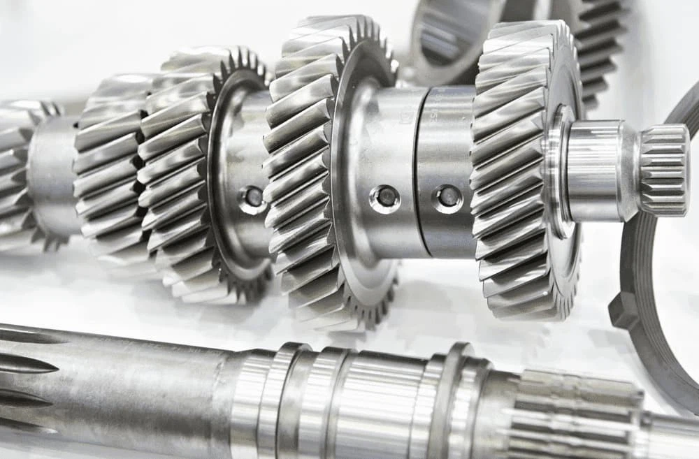
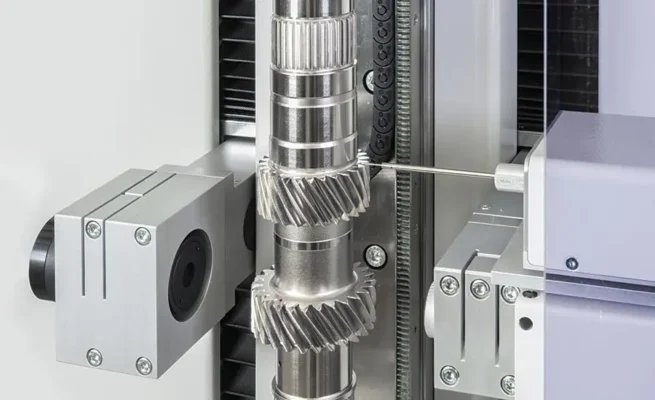
A gear shaft is never just one simple cylinder. In real gearbox design, it is divided into sections, and each section has its own job. One section supports a bearing, another carries a gear, another connects to a coupling or pulley, and another creates a shoulder for axial positioning. That is why a practical gear shaft drawing always shows a series of stepped diameters rather than one uniform value.
In engineering discussion, shaft details often look simple until the assembly starts to take shape. Once gears, bearings, covers, fits, and installation order are brought into the same layout, every shaft step begins to matter. This article explains gear shaft section diameters and lengths in a practical way, using a typical stepped gearbox shaft logic to show why each section is sized differently and how those sizes are tied to real transmission layout.
What gear shaft section diameters are
Gear shaft section diameters are the stepped diameters used to let each shaft section support, position, connect, or transmit load inside a transmission system.
Why this matters
Because each shaft section does a different job.
A bearing seat does not follow the same sizing rule as a gear seat. A shoulder used for axial positioning does not follow the same logic as a coupling end. Once the shaft is divided by function, the dimension sequence starts to make sense.
Because assembly space matters as much as strength.
A shaft can look strong enough on paper and still be troublesome in assembly if the shoulders are too small, the diameter changes are unclear, or the surrounding clearances for bearings, gears, and covers are missing.
Because a gearbox shaft is part of a full system.
Section diameters and lengths are not chosen in isolation. They are shaped by bearing dimensions, gear widths, housing space, cover thickness, coupling requirements, and assembly sequence. That is why stepped shaft design always belongs to the larger transmission layout.
The shaft sections engineers usually define first
| Shaft section | Main purpose | What usually controls it |
| Bearing seat | Support rotation and carry load | Bearing size, fit, and mounting method |
| Gear seat | Mount and locate the gear | Bore size, torque path, and positioning method |
| Shaft shoulder | Stop axial movement and transfer force | Shoulder height and adjacent diameter difference |
| Coupling or pulley seat | Connect outside transmission parts | Hub size, fit, and assembly method |
| End section | Locking, fastening, or retaining | Thread, nut, circlip, or end-cover logic |
The easiest way to read a stepped shaft drawing is not to ask why the diameter changes first. Ask what each section is supposed to do. 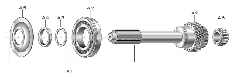
Who usually needs this distinction
- Gearbox design engineers sizing stepped shafts
- Manufacturing engineers preparing turning and grinding routes
- Quality engineers checking bearing seats, shoulders, and fits
- Assembly engineers reviewing installation order and axial positioning
- Buyers comparing custom shaft quotations
- Project teams matching shafts to gears, bearings, and housings
Even when only one engineer creates the drawing, the whole team benefits when each shaft section has a clear purpose.
How section diameters are usually determined
| Design point | Practical meaning | Typical design logic |
| Shoulder used for positioning and force transfer | Needs a clear step to stop axial movement | A larger diameter difference is usually preferred |
| Shoulder used for bearing inner-ring location | Must match bearing installation dimensions | Bearing catalog dimensions often control it |
| Small step used mainly for assembly convenience | Helps parts slide on or off more easily | A smaller difference may be enough |
| Same nominal diameter with different tolerance | Keeps geometry simple while changing fit | Useful when surfaces have different functions |
| Gear shaft section | Must carry both shaft load and gear-related load | Diameter must satisfy mounting and strength together |
In common stepped-shaft design, shoulder diameter changes usually follow the function of the section. For example, when a shoulder locates parts and also carries internal force, engineers often use a more obvious diameter difference, often around 6–10 mm. By contrast, when the step mainly helps assembly or separates machining surfaces, a smaller change of about 1–5 mm may be enough. In some cases, engineers may even keep the same nominal diameter and create the difference through tolerance instead.
Sample Section Diameter Layout
Your sample data shows this design logic clearly. In the gearbox-style arrangement you provided, the high-speed shaft section diameters are 20 mm, 22 mm, 25 mm, 35 mm, 48 mm, 35 mm, and 25 mm. By comparison, the low-speed shaft section diameters are 30 mm, 32 mm, 35 mm, 40 mm, 48 mm, and 35 mm.
This kind of stepped progression is common in shaft design. In general, smaller sections appear where the load is lower, where the design needs a fit transition, or where assembly space matters. In contrast, larger sections usually support the main gear, the bearing seat, or another high-load feature. So even before you calculate detailed stress values, the diameter pattern already shows the job of each section.
How section lengths are usually determined
| Length factor | Why it matters | Typical source |
| Gear-to-housing clearance | Prevents running interference | Gear outside size and housing wall distance |
| Gear side spacing | Leaves room for assembly and oil flow | Gear width and gearbox layout |
| Bearing width | Defines seat length directly | Bearing catalog size |
| Cover or flange thickness | Affects outer support geometry | Housing and end-cover design |
| Coupling or pulley width | Defines external connection section | Mating component size |
Section length design usually starts from surrounding parts, not from the shaft alone. In a practical gearbox layout, values such as gear-to-housing clearance, bearing width, cover thickness, pulley width, and coupling length are typically set first. Only after those values are fixed can the shaft section lengths be finalized.
Sample Section Length Layout
Supplier selection tips for shaft projects
- Do not send only one main diameter and one total length.
For stepped shafts, section-by-section dimensions matter much more than a single overall value. - Show what each section is for.
If the supplier knows which section is a bearing seat, which is a gear seat, and which is a coupling end, the quotation and technical review will be more accurate. - Include surrounding assembly dimensions.
Bearing widths, cover thickness, clearances, pulley width, and coupling length often control the shaft more than the shaft alone. - Clarify fit and tolerance requirements early.
Two sections may look similar in diameter but still need different fits, and that changes machining and inspection planning. - Review the shaft together with the gearbox layout.
A shaft is easier to make correctly when the supplier can see how it works with the gear, bearing, and housing around it.
Why Choose Us
Wenlio Gear supports transmission component projects with a focus on practical geometry, manufacturability, and inspection points that match real assembly use.
For stepped shafts and gear shafts, the key is not only the turned profile itself, but also how each section works with the surrounding gear, bearing, shoulder, and housing structure. That is why section diameters and lengths should always be reviewed as part of the transmission stage rather than as isolated numbers on a drawing.
This kind of function-based dimensional logic makes it easier to move from design review to production and then to stable assembly on site.
FAQ
Q1: Why doesn’t a gear shaft use one constant diameter?
Because different shaft sections do different jobs. Bearings, gears, couplings, and locating shoulders usually need different diameters and different fit logic.
Q2: How is shaft shoulder size usually decided?
It depends on function. A shoulder used for positioning and force transfer usually needs a clearer diameter step than one used only for assembly convenience.
Q3: Can two adjacent shaft sections have the same nominal diameter?
Yes. In some designs, engineers keep the same nominal diameter and use different tolerance values for different functional surfaces.
Q4: What usually controls shaft section length?
The surrounding parts. Gear width, bearing thickness, housing clearance, cover thickness, pulley width, and coupling length often determine the final section lengths.
Q5: Why is stepped-shaft design important in gearbox work?
Because gearbox shafts do more than carry torque. They also support bearings, locate gears, control assembly order, and fit the real housing layout.
Conclusion
A gear shaft becomes much easier to understand once you stop looking for one “main diameter” and start reading it section by section. Each step usually exists for a reason: to seat a bearing, locate a gear, create a shoulder, connect a coupling, or make assembly workable inside a gearbox. Once that logic becomes clear, shaft drawings look less like a list of sizes and more like a map of how the transmission actually works.
If you are reviewing a stepped shaft, preparing a custom shaft RFQ, or checking how a gear shaft should fit into a real gearbox layout, you are welcome to Contact Us with your drawing and application details.