
Blogs, Custom Gear, Gear Shaft
Gears and Shafts: How They Work Together
Apr
Introduction
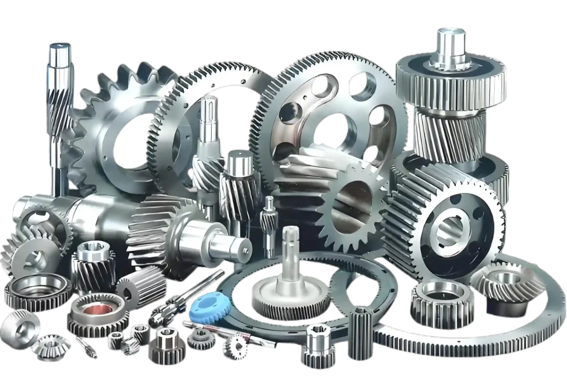
In almost any transmission system, gears and shafts show up as a pair. One handles the meshing and changes how power moves through the system. The other carries that power, supports rotating parts, and keeps everything in position. On a drawing, they may look like separate components. In a working machine, they are part of the same job.
At Wenlio Gear, we often see customers start from only one side of the system. Some begin with gear type and ratio, but have not yet thought through shaft support, fit, or load path. Others focus on shaft structure first, then realize the gear choice will change the whole layout. So it helps to step back and look at both together. This article does that in a practical way: what gears are, what shafts are, the common types of each, and how they work together in real transmission systems.
What gears and shafts are
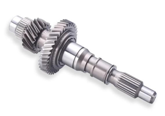
A gear is a toothed component that transfers power by meshing with another gear. A shaft is a rotating member that supports parts like gears and pulleys while carrying torque through the system.
Why they need to be understood together
Because one part alone does not explain system performance.
A gear may be the part that changes speed or direction, but it still needs a shaft to support it, position it, and transmit the load. In the same way, a shaft may carry torque, but without gears it cannot create the ratio change many machines depend on.
Because the real problems usually happen between them.
Noise, wear, poor contact, vibration, fit problems, and early failure are often not caused by one component alone. They come from the way the gear, shaft, bearing support, and housing work together.
Because layout decisions affect both from the start.
As soon as a project chooses parallel shafts, intersecting shafts, or offset shafts, it is already making decisions about both gear form and shaft function. That is why these parts are best discussed as one transmission stage, not as two isolated parts.
Common gear and shaft types at a glance
| Component | Type | Typical use | Main note |
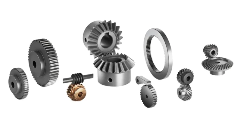
| Gear | Spur gear | Simple parallel-shaft transmission | Easy to make, but noisier at speed |
| Gear | Helical gear | Smoother parallel-shaft transmission | Runs quieter, but adds axial force |
| Gear | Bevel gear | Intersecting-shaft transmission | Useful for changing direction |
| Gear | Worm and wheel | High reduction in compact layouts | Smooth running, but more sliding |
| Gear | Planetary gear | Compact, high-ratio transmission | Strong load sharing in limited space |
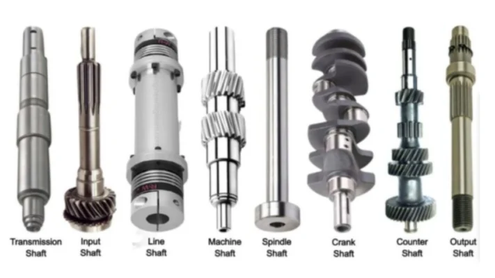
| Shaft | Input shaft | Receives power into the system | Starting point of torque flow |
| Shaft | Output shaft | Delivers adjusted speed and torque | Final transmission member |
| Shaft | Intermediate shaft | Transfers power between stages | Common in multi-stage gearboxes |
| Shaft | Solid / hollow shaft | Depends on stiffness and weight target | Structure affects rigidity and mass |
| Shaft | Spline / gear shaft / drive shaft | Depends on torque path and assembly method | Chosen by connection and function |
This is only a starting map. In real applications, the right choice depends on how the full transmission stage is expected to run.
Where they are commonly used
- Automotive transmission systems
- Agricultural machinery drivetrains
- Construction equipment gearboxes
- Industrial automation equipment
- Heavy-duty truck transmission systems
In all of these areas, gears and shafts do more than simply fit together. They need to match torque, speed, support method, lubrication, space limits, and expected service life.
A tractor gearbox, for example, may face shock loads, contamination, and long field duty. A servo reducer in automation may care more about smooth motion, backlash control, and compact packaging. A truck transmission stage may focus on durability, alignment stability, and repeatable torque transfer over long mileage. The basic parts are still gears and shafts, but the design priorities change with the application.
That is one reason why transmission parts should be reviewed in context. Two gear-and-shaft sets can look similar in size and still be built for completely different working conditions.
What each one contributes in a real transmission system
| Component | Main role | What it changes in the system |
| Gear | Meshing transmission element | Speed, torque, direction, ratio |
| Shaft | Rotating support and torque carrier | Position, stiffness, alignment, load transfer |
| Gear + shaft together | Functional transmission stage | Real running behavior, assembly stability, durability |
A simple way to think about it is this:
the gear decides how power changes,
the shaft decides how that power is carried and supported.
Take a gearbox as an example. The input shaft brings power into the housing. A gear mounted on it passes motion to another gear. That second gear may sit on an intermediate shaft, which carries the next load path through the system. The output shaft then delivers the new speed and torque to the next component. So even in a straightforward gearbox, the result depends on both meshing and support working together.
What good matching between gears and shafts improves
| Design goal | What improves | Why it matters |
| Smoother transmission | Better meshing and support | Lower noise and vibration |
| Higher load capacity | Better force path through teeth and shaft | More reliable torque transfer |
| Better assembly consistency | Clear fit and positioning logic | Fewer installation issues |
| Longer service life | Better alignment and lower stress concentration | Less wear and fewer failures |
| More practical manufacturing | Better fit between geometry and process route | Easier production and inspection |
When a transmission works well in the field, it is usually because the gear design, shaft structure, and assembly logic are supporting the same objective.
Supplier selection tips
- Do not discuss the gear without the shaft layout.
Ratio and tooth form matter, but so do support span, mounting style, and the way the shaft carries load. - Clarify whether the shaft is separate or integrated.
A plain shaft, spline shaft, drive shaft, and gear shaft are not the same thing. The function needs to be clear from the beginning. - Include fit and positioning details in the RFQ.
Keyways, splines, bearing seats, shoulders, and axial locating features often matter just as much as the gear itself. - Match the process route to the real duty cycle.
A heavy-duty transmission stage may need a completely different material, heat treatment, and inspection plan from a light industrial drive. - Review the whole stage, not one part at a time.
A good supplier should want to understand how the gear and shaft work together in the application, not only what one isolated component looks like.
Why Choose Us
Wenlio Gear supports transmission projects with a focus on practical geometry, shaft integration logic, and inspection evidence that fits real use conditions.
For gear-and-shaft programs, we help customers connect component design with transmission function. That includes choosing the right gear type for the shaft layout, checking how torque moves through the system, and aligning manufacturing and inspection with the real application target.
We also try to make the path from drawing review to production clearer. In practice, that means reducing the gap between what looks correct on paper and what performs reliably after assembly.
FAQ
Q1: What is the main difference between a gear and a shaft?
A gear changes speed, torque, or direction through meshing. A shaft supports rotating parts and carries torque through the system.
Q2: Can a shaft work without a gear?
Yes, but only for simple torque transfer. Without gears, it cannot provide the same kind of ratio or direction change that many machines require.
Q3: Which gear type is the most common?
That depends on the application. Spur, helical, bevel, worm, and planetary gears are all common, but each suits a different layout.
Q4: What is a gear shaft?
A gear shaft is a part where the gear and shaft are integrated into one structure. It is often used where rigidity, compactness, or alignment control matters.
Q5: Why do gear-and-shaft projects fail in practice?
Common reasons include poor alignment, incorrect fit, wrong gear type for the shaft layout, weak support, and not looking at the full transmission stage as one system.
Conclusion
Gears and shafts do different jobs, but in real machines they work as one transmission unit. Gears create the ratio, the direction change, and the meshing action. Shafts support those parts, carry torque, and keep the rotating system stable. Once that relationship is clear, design decisions become easier and RFQs become more accurate.
If you are selecting gears, shafts, or a complete transmission stage for your application, you are welcome to Contact Us with your drawings and operating conditions so we can help align component choice with a practical manufacturing and inspection plan.
Pingback: Gear Shaft Section Diameters Explained - wenlio.com