
Blogs
How to Calculate Gear Module?
Dec
1.Conclusion
When you work with metric gears, gear module is one of the key numbers you need to know. It describes tooth size, links the pitch diameter with the number of teeth, and determines whether two gears can mesh correctly and carry the required load.
At Wenlio Gear, we deal with module every day when designing and manufacturing gears for agricultural machinery, heavy-duty trucks, construction equipment, electric vehicles and industrial automation. This guide explains what module is, how to calculate it from real parts, and how it can help you select or identify gears in practice.
2. What is gear module?
In the metric system, gear module (m) is defined as the pitch diameter divided by the number of teeth:
m = d / z
m = module (mm per tooth)
d = pitch diameter (mm)
z = number of teeth
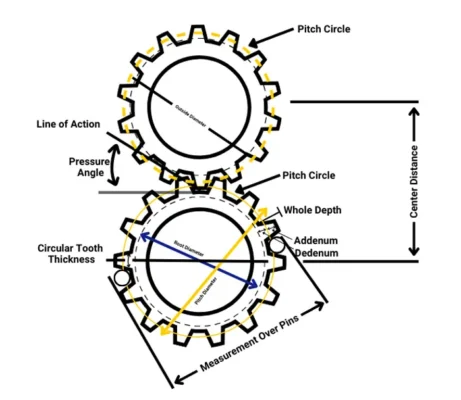
The pitch circle is the imaginary circle where two gears roll together and transmit motion. In simple terms, module tells you “how big each tooth is”:
Larger module → bigger, stronger teeth and a larger pitch diameter for the same tooth count
Smaller module → finer teeth, more compact gears, often better suited for high-speed and compact drives
Two gears can only mesh correctly if they have the same module, the same pressure angle and a compatible tooth profile.

3. Module and diametral pitch (metric vs imperial)
In inch-based systems, tooth size is often given as diametral pitch (DP), which is “teeth per inch of pitch diameter”. Module and diametral pitch are related by:
m = 25.4 / DP
DP = 25.4 / m
Here, module m is in millimetres, and DP is in teeth per inch.
This conversion is useful when you have an imperial drawing or a DP marking on a gear, but your project uses metric gears. You can convert DP to module, then round to the nearest standard metric module.
4. How to find module from an existing gear
If you have a gear in your hand and no drawing, you can still estimate module with basic tools. The following method assumes a standard full-depth spur gear (or a helical gear measured in the transverse plane).
4.1 Count the teeth
Mark one tooth with a pen and count around the gear until you return to the mark. This gives you the tooth count z. It is worth counting twice to avoid simple mistakes.
4.2 Measure the outside diameter
Use a caliper to measure the outside diameter Dₒ of the gear as accurately as possible. For a standard full-depth gear (20° pressure angle), the outside diameter is related to module and tooth count by the approximate standard formula:
Dₒ = m (z + 2)
Rearranging gives a very useful expression for module:
m = Dₒ / (z + 2)
This works well for many standard gears and is widely used in workshop practice to identify module.
4.3 Compare with standard module values
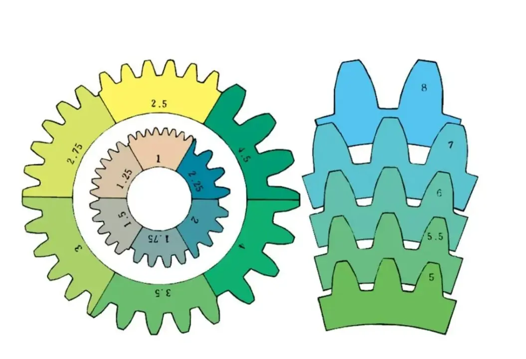
Once you have calculated m, compare it with standard module values such as:
1.0, 1.25, 1.5, 2.0, 2.5, 3.0, 4.0, 5.0, 6.0, 8.0, 10.0 …
If your result is very close to one of these (for example 2.48 mm vs 2.50 mm), it is almost always safe to treat the gear as that standard module and assume the difference comes from measurement tolerances or wear.
5. How to calculate module from centre distance
In many reverse-engineering situations, you know the centre distance (a) between two shafts and the tooth counts on each gear, but you cannot easily measure the gear diameters.
For two standard gears with the same module, the centre distance is:
a = (m / 2) · (z₁ + z₂)
Rearranging gives:
m = 2a / (z₁ + z₂)
This method is especially useful when you have a gearbox housing with a fixed centre distance and you want to check which module will fit, or when you are verifying the module of an existing gear pair using only the housing and tooth counts.
6. Typical module ranges and applications
Module selection is always a balance between load capacity, available space and speed. The table below gives typical ranges and where they are commonly used (not strict limits, but useful guidance).
| Module (mm) | Typical use case |
| 0.5 – 1.0 | Small instruments, light-duty precision mechanisms |
| 1.0 – 2.0 | Small machinery, auxiliary drives, light industrial gearboxes |
| 2.0 – 3.5 | General machinery, automotive auxiliary gear sets |
| 4.0 – 6.0 | Agricultural gearboxes, truck drives, construction machinery gear sets |
| ≥ 6.0 | Very heavy-duty, slow-running large gears and open gear drives |
For Wenlio Gear, many customer projects in our five core sectors fall into the 2.0–6.0 mm range. Module is always chosen together with material, heat treatment, gear accuracy and lubrication to reach the required torque capacity, lifetime and noise level.
7. Common mistakes when working with module
In real projects, we often see similar problems when people estimate or use module:
Treating outside diameter as pitch diameter, and putting Dₒ directly into m = d / z
Mixing metric module and DP without proper unit conversion
Ignoring standard module series and assuming “2.47 mm” must be a special size
Checking only one gear of the pair, when the other gear may already have been replaced incorrectly in the past
Careful measurement, cross-checking with centre distance, and comparing with standard module values can avoid most of these issues.

8. How Wenlio Gear can support your project
If you only have partial information, such as tooth counts, an estimated outside diameter, a known centre distance or a worn sample gear, Wenlio Gear can help you work backwards to identify a realistic module and design a stronger, more reliable replacement.
As a precision gear manufacturer and custom gear supplier, we design and produce bevel gears, cylindrical gears and gear shafts for agricultural machinery, heavy-duty trucks, construction equipment, EV drives and industrial automation systems. Our engineers are used to working from measurements, photos and samples, not just from ideal CAD models.
9. Conclusion
Gear module is a simple concept, but it plays a central role in gear design, selection and replacement. Understanding how to calculate module from tooth count, outside diameter and centre distance makes it much easier to check compatibility, size gears logically and communicate clearly with your gear supplier.
If you are trying to identify the module of an existing gear, redesign a gearbox or plan a new driveline, Wenlio Gear is ready to support you with both engineering know-how and manufacturing capability. You can share your project details with our team via the Contact Us page, and we will help you turn your requirements into a clear and manufacturable gear solution.
10. FAQ – Quick questions about gear module
Q1. Can gears with different modules mesh together?
No. If modules are different, tooth spacing does not match. Even if the gears seem to touch, contact is wrong and damage will occur quickly.
Q2. How accurate does my module calculation need to be?
For most practical work, identifying the nearest standard module to two decimal places is enough. The goal is to match a standard value, not to chase tiny differences.
Q3. Does a higher module always mean a stronger gear?
Larger module usually means a stronger tooth, but overall strength also depends on material, heat treatment, face width and quality. A smaller module with better steel and heat treatment can still be adequate in many compact drives.
Q4. What should I do if my result falls between two standard modules?
Re-check your measurements and formulas. If it still sits between standard values, you may be dealing with a non-standard design or a worn gear. In such cases, sharing detailed measurements or physical samples with Wenlio Gear is the safest way to confirm the module.
Pingback: Reference Circle vs Pitch Circle in Gears Explained
Pingback: What Is Module of a Bevel Gear - wenlio.com