
Blogs, Gear Shaft
Transmission Input Shafts: Function, Parts and Materials
Mar
Introduction
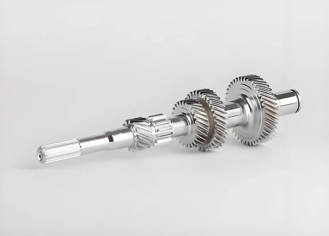
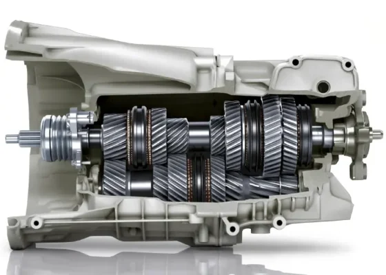
Transmission input shafts sit at the start of the drivetrain power path, connecting the engine or motor to the transmission’s internal gearing. As a result, they shape how smoothly torque enters the system. So even though the term sounds simple, input shaft design can influence shifting feel, noise, wear, and long-term durability.
Building on Wenlio Gear’s experience with shafts and splined components, this guide explains input shafts in a practical, structured way—from a one-line definition to types, key design features, materials, and what to share for an accurate RFQ.
What an Input Shaft Is
An input shaft is the rotating shaft that transfers power from the engine or motor side into the transmission gear system.
Why Input Shafts Matter
They define the “first torque handoff”
The input shaft is the first mechanical link that delivers torque into the transmission. So if spline fit, bearing seats, or alignment drift, the drivetrain often “feels” it quickly as heat, rattle, vibration, or accelerated wear. In other words, a small geometric issue near the input can cascade into larger downstream symptoms.
They influence shifting quality and component life
In manual and synchronized designs, stable shaft rotation and controlled fits help the synchronizer and gear engagement behave consistently. When the input shaft runs true and the spline interface fits correctly, shifts tend to feel smoother. At the same time, the system avoids unnecessary micro-sliding that can trigger fretting or spline wear over time.
They operate under demanding conditions
Input shafts see frequent torque reversals, wide speed ranges, and repeated start/stop events. Meanwhile, lubrication changes with temperature, which can increase sensitivity to surface finish and hardness. As a result, input shaft durability depends on system-level alignment—material, heat treatment, and precision control—rather than on any single dimension.
Common Input Shaft Types
In practice, “input shaft” can mean slightly different things across manual, DCT, automatic, and EV layouts. So the quickest way to align expectations is to map the shaft to its power path and the feature that defines fit and support.
| Type | Typical layout | Where you see it |
| Manual transmission input shaft | Engine → clutch → input shaft | Passenger & commercial manuals |
| Dual-clutch input shafts (DCT) | Engine → dual clutches → two input paths | Performance cars, some hybrids |
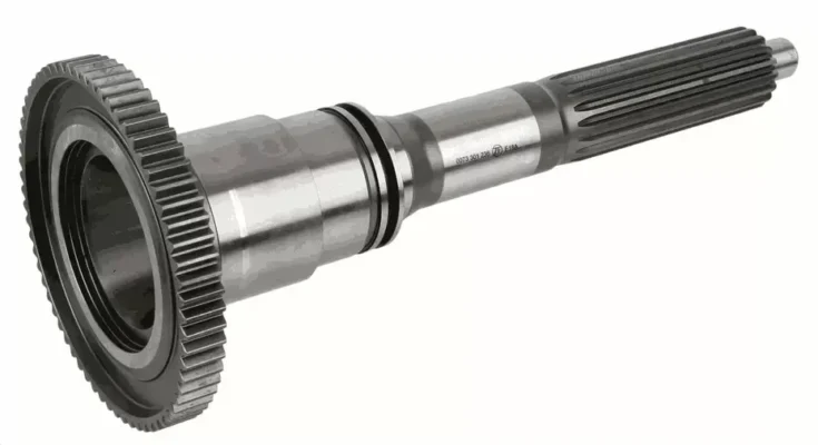
| Automatic/planetary “input member” shaft | Engine → torque converter → geartrain input member | Many automatics |
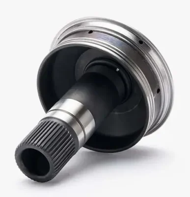
| EV drive unit input shaft (simplified) | Motor → reduction stage | EV e-axles and drive units |
| Hollow input shaft (design variant) | Coaxial packaging | DCTs, some automatics |
In short, manual and DCT input shafts emphasize spline fit and coaxial support for consistent engagement. Meanwhile, automatic and EV layouts often rename the part (input member/turbine shaft), but the same fundamentals still apply: stable bearing seats, controlled runout, and repeatable fit.
Note: “Input shaft” is most specific in manual and DCT systems. In many automatics, OEMs may describe a turbine shaft or input member instead. Still, the engineering requirements remain similar: reliable torque transfer, stable support, and consistent fit.
Where Input Shafts Are Used
Input shafts show up across many drivetrains, including:
-
Manual transmissions (passenger, LCV, and heavy-duty manuals)
-
Dual-clutch transmissions with dedicated input paths
-
Automatic transmissions (where the shaft may act as an input member/turbine shaft, depending on layout)
-
EV drive units (especially high-speed input/reduction interfaces)
-
Off-highway and agricultural equipment using multi-shaft geartrains
-
Rebuild and aftermarket programs replacing worn or damaged shafts
In practice, rebuild programs usually prioritize fit repeatability and interchangeability—splines, bearing seats, and seal surfaces. By contrast, OEM programs more often emphasize noise and durability targets, along with tight control of variation across production lots.
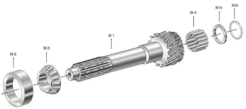
Key Design Features That Affect Performance
Once you’ve identified the layout, performance usually comes down to a handful of features that control alignment, contact, and lubrication. In other words, these are the levers that make prototypes behave like production parts.
| Feature | What it controls |
| Spline geometry and fit | Defines torque transfer and engagement stability (impacts: Wear, rattle/noise, assembly consistency) |
| Bearing journals/seats | Support rotation and reduce friction (impacts: Heat, vibration, bearing life) |
| Seal surfaces | Keep lubricant in and contamination out (impacts: Leakage risk, durability) |
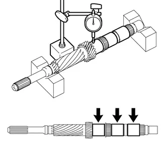
| Runout and coaxiality | Controls alignment with mating parts (impacts: Noise, abnormal wear, shifting feel) |
| Surface finish | Affects contact stress and friction (impacts: Wear rate, fretting/scuffing risk) |
| Heat treatment strategy | Balances hardness and core toughness (impacts: Fatigue life, crack resistance) |
| Lead-in chamfers & spline relief | Helps assembly and reduces edge loading (impacts: Assembly ease, reduced spline damage) |
| Oil feed features (if used) | Supports lubrication to bearings/contacts (impacts: Temperature control, wear reduction) |
| Integral gear features (some designs) | Integrates a gear with the shaft (impacts: Part count, stiffness, NVH sensitivity) |
As a rule, spline fit and runout drive the biggest “feel” differences first, because they set alignment and micro-sliding at the entrance of the system. Then surface finish and heat-treatment choices decide how quickly that interface wears in—or wears out.
A useful rule: when the shaft spins fast and carries fluctuating torque, runout control, spline fit, and heat treatment usually drive real-world performance. Meanwhile, small detail features (chamfers, relief, surface finish) often decide whether an assembly feels smooth or “fussy” during installation and early operation.
Practical Benefits of a Well-Specified Input Shaft
So what does this look like in service? The table below links key specifications to outcomes you can feel on the bench and in the field.
| Goal | What you gain in service |
| Smooth power delivery | Stable torque transfer into gear system — Reduces harshness and shock loading |
| Lower wear | Better fit and surface condition — Extends life of splines and mating hubs |
| Reduced noise and vibration | Controlled runout and bearing support — Improves NVH stability |
| Better sealing reliability | Proper seal surfaces and finish — Prevents lubricant loss and contamination |
| Repeatable assembly | Clear tolerances and inspection plan — Lowers rebuild/OEM variability |
| Easier serviceability | Clear datums and fit callouts — Reduces rework during rebuild |
Therefore, the right spec saves cost twice: you reduce rework during build, and you reduce early wear mechanisms during service. To lock these benefits in, align early on spline fit ownership, datum strategy, and the inspection evidence that best reflects functional fit.
In other words, the “right” specification saves cost twice: once during assembly and again during service life, because it reduces variation and prevents early wear mechanisms from starting.
Supplier Selection Tips
-
First, confirm spline definition and mating-fit expectations: spline type, tooth form, fit class (if applicable), and which mating part defines the functional fit.
-
Next, set material and heat-treatment targets tied to the duty cycle: hardness targets plus case/core expectations based on torque cycles, shock risk, and lubrication temperature.
-
Then, align datums, runout, and bearing-seat requirements: agree on functional datums and the runout/coaxiality controls that matter most for NVH and durability.
-
In parallel, define inspection deliverables and acceptance methods: dimensional report, runout checks, hardness results, and the spline-fit verification approach (gage strategy or mating check).
-
Finally, share application conditions for validation: speed/torque range, duty cycle, lubrication assumptions, and any failure symptoms (wear, noise, fit, leakage).
Why Choose Us
Wenlio Gear manufactures precision shafts and splined components for drivetrain and industrial transmission applications. For input shaft programs, we support custom spline geometry, controlled heat-treatment planning, and inspection workflows built around real assembly datums.
In practice, we prioritize fit consistency at splines, runout control, and surface condition so that prototypes and production batches behave the same way in real installations. To get started, contact us with your drawing (or a sample) and operating conditions, and we’ll propose a manufacturability route plus an inspection plan.
To further reduce risk, we help teams align the key “handoff points” early—what the shaft mates to, how the assembly defines datums, and which inspection evidence best reflects functional fit. As a result, iteration loops typically shorten and batch repeatability improves.
FAQ
Q1: Is an input shaft the same as a drive shaft?
A: No. The input shaft delivers power into the transmission, whereas the drive shaft (propeller shaft) delivers power from the transmission to the differential and wheels.
Q2: Do all vehicles have an input shaft?
A: Manual transmissions clearly use an input shaft. Meanwhile, automatics and EV drive units may use different terms (for example, input member or turbine shaft). Even so, they still rely on an input-side rotating element to deliver power into the gear system.
Q3: Why do splines matter so much on input shafts?
A: Splines carry torque through multiple teeth. So if fit is off, surface condition is weak, or alignment drifts, the interface can develop fretting, rattle, and early engagement damage—especially when torque fluctuates or lubrication runs hot.
Q4: What typically causes early input shaft wear?
A: In practice, the most common drivers include poor lubrication or contamination, plus misalignment/runout issues, improper spline fit, or a hardness profile that doesn’t match the duty cycle.
Q5: What should I send for a fast RFQ?
A: To move fast, send a drawing or sample, spline standard/details, material and heat-treatment targets, datums and runout limits, speed/torque range, and lubrication assumptions.
Conclusion
Input shafts may look like simple rotating parts, but they strongly influence drivetrain stability. So the right spline geometry, bearing support, sealing surfaces, and heat-treatment strategy help the transmission deliver smooth torque, reduce wear, and keep shifting performance repeatable.
If you’re developing an input shaft, replacing a worn part, or troubleshooting fit and runout in a drivetrain program, then Contact Us with your drawing (or a sample) and operating conditions. From there, we can align on a practical manufacturing route and an inspection plan that matches real assembly datums.