
Blogs, Helical Gear
What Is a Herringbone Gear?Benefits Uses and Selection
Feb
Introduction
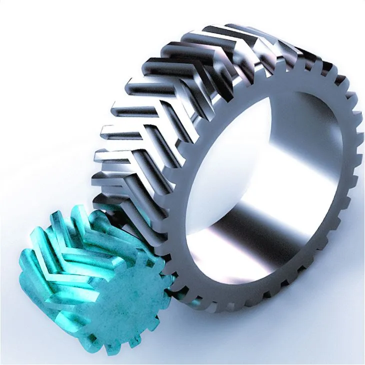
A herringbone gear is a helical gear form that combines left hand and right hand helices on one gear blank, creating a V pattern across the face width. It aims to keep smooth helical engagement while balancing the axial thrust that a single helical gear typically generates.
In Wenlio‘s guide explains what the term means in practice, how it differs from double helical gears, where it is used, and the selection points that most often decide noise, temperature rise, and service life.
What is a herringbone gear
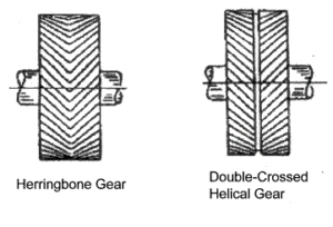
Herringbone gear and double helical gear are closely related designs built from two mirrored helical tooth sets of opposite hand. A common distinction is whether the tooth sets meet continuously in the middle or are separated by a groove.
Herringbone gear vs double helical gear
| Term | What it usually means | Why it matters |
| Herringbone gear | Opposite helices with no central gap. The tooth trace is continuous. | Higher manufacturing difficulty. Often chosen when smoothness and thrust balance are priorities. |
| Double helical gear | Opposite helices with a central groove between halves. | Groove provides tool clearance and can simplify cutting while keeping thrust balancing benefits. |
Why axial thrust is reduced
A single helical gear generates axial thrust because the helix angle creates a force component along the shaft. With opposing helix hands, thrust forces act in opposite directions and can largely balance when load sharing is even.
In real systems, balance depends on alignment and stiffness. If one half carries more load due to deflection or assembly offset, some thrust can remain and contact can shift toward one side.
Where herringbone gears are used
These gears are common in heavy duty, continuous running applications where smooth torque transfer and stable alignment matter.
- Heavy duty parallel shaft drives with high torque and long duty cycles
- Large reducers in mining, cement, and rolling equipment
- Marine and industrial power transmission stages where thrust control supports stability
- Noise sensitive high load applications where smoother engagement is valuable
Herringbone gears compared with spur and helical gears
On the simplicity spectrum, spur gears are simple but can be noisier at speed. Helical gears run smoother but introduce thrust. Double helical and herringbone gears aim to keep smoothness while balancing thrust, with higher complexity and cost.
Quick comparison
| Gear type | Smoothness | Axial thrust | Difficulty | Typical fit |
| Spur | Moderate | Low | Low | General purpose, cost sensitive drives |
| Helical | High | High | Moderate | Higher speed drives, thrust bearings needed |
| Double helical | High | Balanced | High | Heavy duty drives needing smoothness with reduced thrust |
| Herringbone | Very high | Balanced | Very high | High power continuous drives where stable contact is critical |
Key benefits and limits
Benefits
| Benefit | What it means | Practical impact |
| Axial thrust balance | Opposite helix hands offset thrust forces | Lower net thrust load when load sharing is even |
| High contact ratio | More teeth share load | Smoother torque transfer and reduced vibration tendency |
| High load capacity | Larger effective contact area | Suited for heavy duty continuous service |
| Noise potential | Progressive engagement | Can support quieter operation when alignment and lubrication are correct |
Limits
| Limit | Why it happens | What to plan for |
| Harder to manufacture | Complex geometry and clearance limits | Higher cost vs spur or simple helical gears |
| Alignment sensitivity | Two halves must share load evenly | Define mounting references and support stiffness early |
| Lubrication sensitivity | High load needs stable oil film | Choose oil by temperature and duty cycle |
| Not always necessary | Benefits may not justify cost | Standard helical can be sufficient in light duty drives |
Design and terminology notes
These terms often appear in drawings and discussions. Understanding them helps you specify a stable design.
| Term | Meaning | Why you care |
| Helix angle | Angle of the tooth line relative to the gear axis | Affects smoothness and sliding behavior |
| Face width | Tooth width along the axis | Wider faces can carry more load but need good alignment |
| Backlash | Intentional clearance between tooth flanks | Too tight causes heat, too loose causes impact and noise |
| Runout | Radial or axial variation during rotation | Can create cyclic noise and uneven load sharing |
Lubrication and thermal stability
Lubrication is critical because it supports film formation, reduces friction, and helps keep efficiency stable in high-power drives.
First, oil viscosity should match the actual operating temperature. If the oil is too thick, churning losses increase; if it is too thin, film strength drops.
In addition, oil delivery should match speed and load. Splash lubrication works well in many reducers, while higher-duty applications may need directed lubrication. At the same time, temperature rise should be watched closely, since it can be an early sign of misalignment, tight backlash, or lubrication mismatch.
Common wear patterns to watch
The most common symptoms often point to a small set of root causes. Early diagnosis reduces downtime.
| Symptom | Likely issue | Typical causes | What to check |
| Hot running | High friction or scuffing risk | Backlash too tight, misalignment, oil mismatch | Backlash, alignment, oil grade and delivery |
| Local pitting near one edge | Edge loading | Deflection or mounting error | Contact location, support stiffness, lead control |
| Uneven wear between helix halves | Unbalanced load sharing | Assembly offset or shaft bending | Axial positioning, deflection under load |
When to choose a grooved double helical design
In many industrial reducers, a double helical gear with a central groove is a practical alternative to a true no gap herringbone gear. It can deliver most of the thrust balancing benefit while making manufacturing and inspection more straightforward.
- Choose a grooved design when tooling clearance and lead time are key constraints.
- Choose a grooved design when the application can tolerate a small separation between helix halves.
- Consider a no gap herringbone design when the highest smoothness targets justify added complexity.
Inspection points that support repeatability
For heavy duty gearsets, repeatability is often decided by what is measured, not only by what is drawn. Even if you do not specify a full gear accuracy class, it helps to align on a few practical checks.
- Backlash range at assembly or at a defined measurement radius
- Runout and datum scheme so the gear seats predictably on the shaft
- Tooth flank condition and contact location when performance is sensitive
Selection notes that prevent surprises
- Decide whether thrust reduction is a primary requirement. If not, standard helical gears may be enough.
- Check stiffness of shafts and housing. Deflection can shift contact and reduce thrust balancing.
- Define duty cycle and thermal window so lubrication assumptions match reality.
- Specify backlash range and mounting references so acceptance is measurable.
- Align acceptance checks such as geometry, runout, and surface condition with the performance target.
Supplier selection tips
- Ask how load sharing between the two helix halves is verified.
- Ask how backlash and runout are measured and controlled.
- Ask what lubrication window is assumed for your speed and load range.
- Ask what acceptance criteria will be used to avoid installation surprises.
Why choose Wenlio Gear
- Application focused guidance to choose between helical, double helical, and herringbone designs.
- Precision gear capability for heavy duty power transmission parts across multiple industries.
- Clear acceptance alignment to support repeatable installation and stable operation.
- Confidential workflow for drawings and project information when required.
FAQ
Q:Is a herringbone gear the same as a double helical gear
They are closely related. Many teams use the terms interchangeably. A strict definition often treats herringbone as a continuous V with no central gap, while double helical commonly includes a groove for tool clearance. Clarify which form is acceptable for your project.
Q:Do herringbone gears eliminate axial thrust completely
They are designed to balance thrust, but the net result depends on alignment and load sharing between the two helix halves. Misalignment or deflection can leave some thrust and shift contact.
Q:Why are herringbone gears more expensive than standard helical gears
They are more complex to manufacture and often require tighter process control and inspection. The added cost is usually justified in heavy duty or noise sensitive systems.
Q:Where do herringbone gears provide the biggest value
In heavy duty parallel shaft drives where smooth running and thrust management support long service life, especially in large reducers.
Q:What should I define early for a stable design
Duty cycle, speed and torque range, mounting references, backlash target, lubrication method, and acceptance checks.
Conclusion
Herringbone and double helical gears are thrust balanced helical gears used for smooth, heavy duty power transmission. They can reduce net axial thrust and support stable load sharing, but they still require good alignment, realistic lubrication assumptions, and measurable acceptance criteria.
Contact Us to share drawings and operating conditions so gear form, tolerances, lubrication assumptions, and acceptance approach can be aligned early.