
Blogs, Bevel Gear, Planetary Gear
The Differences Between Bevel Gears And Planetary Gears

Feb
Introduction
Bevel gears and planetary gears both transfer torque, yet they solve different design problems. Bevel gears are built for intersecting shafts and for changing the direction of power. Planetary gears, in contrast, are often chosen for compact coaxial layouts, flexible ratios, and strong torque density.
At Wenlio Gear, we focus on measurable, manufacturable bevel gear solutions (straight bevel, spiral bevel gears, zerol bevel, and hypoid gears). This guide shows how to compare bevel gears vs planetary gears using practical decision points: shaft layout, ratio targets, torque density, gear noise, assembly sensitivity, and cost.
Quick comparison in one line
- Choose bevel gears when the key need is a shaft angle change (direction change).
- Choose planetary gear trains when the key need is compact ratio and torque density (load sharing).

Types you’ll typically specify
Bevel gear families
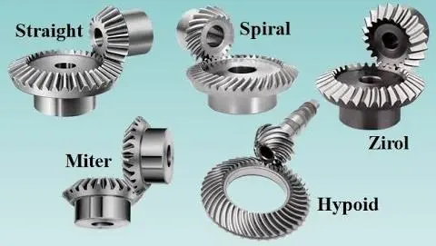
First, straight bevel gears have a simpler tooth form and usually cost less, so buyers often choose them for lower-speed applications or projects with less demanding noise requirements.
Next, spiral bevel gears engage more smoothly and usually run quieter at higher speeds, but they also require more complex manufacturing.
Then, zerol bevel gears sit somewhere in between. They can offer a balance between smoother running and lower manufacturing complexity.
Finally, hypoid gears belong to the bevel gear family as well, but their axes do not intersect because they use an offset layout. This can help with packaging and load distribution, although it also brings more sliding into the meshing process.
Planetary gear train families
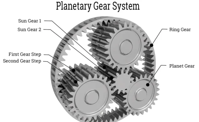
A planetary system is a gear arrangement, not just a single gear. It usually includes a sun gear, planet gears, a ring gear, and a carrier.
First, a single-stage planetary gives you a compact ratio stage and spreads the load across multiple planets. Next, a multi-stage planetary adds more ratio within a short overall length by stacking stages together. In some cases, designers also use a compound or stepped planetary layout when they need a special ratio or a tighter packaging solution.
Key characteristics that drive the decision
| Decision point | Bevel gears | Planetary gear trains |
| Primary function | Change power direction between intersecting shafts | Provide ratio + torque density via load sharing |
| Typical shaft layout | Intersecting shafts (often 90°); hypoid adds offset | Often coaxial input/output (depends on which member is fixed) |
| Part count | Usually a matched gear pair (two main gears) | Multiple gears + carrier + ring (more parts) |
| Load sharing | Single mesh pair carries most load at a time | Multiple planets can share load (when designed/assembled correctly) |
| Noise & smoothness | Spiral bevel is typically smoother than straight | Can be smooth, but sensitive to carrier rigidity and tolerance stack-up |
| Efficiency drivers | Sliding/rolling balance, contact, lubrication | Mesh + bearing losses + load-sharing accuracy |
| Manufacturing/assembly sensitivity | Contact pattern and mounting distance are critical | More sensitive to tolerance stack-up and planet load balance |
| Cost tendency | Often lower for simple direction-change stages | Often higher due to part count and precision assembly needs |
Supplier selection tips
First, start with the layout. Ask whether the system needs a shaft angle change, which points to bevel gears, a compact ratio stage, which points to planetary gears, or a combination of both.
Next, define the top one or two priorities as early as possible. In most projects, that means noise, temperature rise, efficiency, service life, or packaging space.
Then, share the real operating conditions. Give the supplier the actual speed range, torque range, duty cycle, shock load level, and working temperature range so they can review the design on the right basis.
After that, make the project scope clear. Explain whether you need a matched bevel gear set, individual planetary components, or a complete integrated gear stage, and also state which acceptance checks will decide approval.
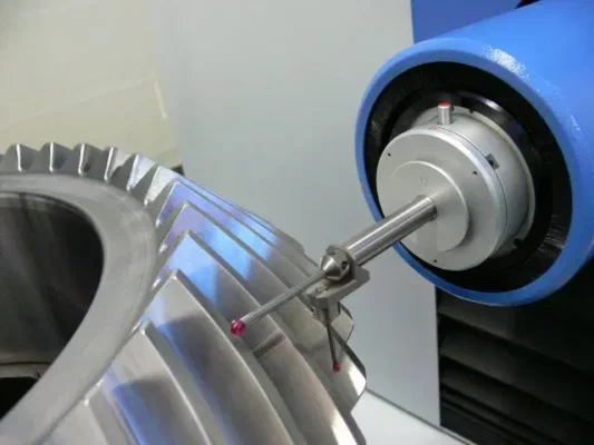
Finally, ask how the supplier controls repeatability. A good review should cover key datums, runout and alignment control, and any method used to verify contact pattern or load sharing.
Why Choose Us
Wenlio Gear provides precision gear solutions for industrial power transmission needs, including bevel gear sets and gear components used in planetary gear trains (sun/planet/ring gears as required by project design).
We support customers with:
- Clear specification alignment (geometry, targets, and acceptance checks)
- Manufacturing route recommendations matched to performance goals
- Inspection planning that reflects real assembly needs
- Practical RFQ support to reduce back-and-forth and speed up decision-making
FAQ
Q1: Are bevel gears only for 90-degree drives?
No. 90° is common, but bevel gears can be designed for many intersecting shaft angles.
Q2: Why do planetary gears deliver high torque density?
Multiple planets can share load, and the coaxial layout packs torque capacity into a compact space.
Q3: Which is quieter: bevel gears or planetary gears?
It depends on tooth form, accuracy, surface finish, and alignment. Spiral bevel gears or zerol bevel gears can be quiet, and well-built planetary gearsets can also be low-noise when load balance is controlled.
Q4: What should I send for an accurate quote?
A drawing or 3D model, torque/speed range, duty cycle, lubrication method, mounting constraints, noise target, and material/heat-treatment expectations.
Q5: What commonly reduces bevel gear life early?
Misalignment or incorrect mounting distance that shifts the contact pattern and concentrates stress.
Conclusion
Bevel gears are typically the most direct solution when you need angle transmission and a clean change in drive direction. Planetary gears are often a better fit when compact coaxial packaging, high torque density, and flexible ratios are the priority—while also requiring tighter control of tolerances and assembly alignment.
If you’re evaluating a project, Contact Us to share your drawings and operating conditions (torque, speed, duty cycle, lubrication, mounting constraints, and noise target) so the gear form, tolerances, heat-treatment route, and lubrication assumptions can be aligned early—before changes become expensive.
