
Blogs
Reference Circle vs Pitch Circle in Gears Explained
Mar
Introduction
In gear design, drawings and standards rely on fixed geometry, but real assemblies operate with tolerances, load deflection, and center-distance variation. That is why two similar terms—reference circle and pitch circle—often create confusion. Engineers may use them interchangeably in casual discussion, yet they serve different roles in gear geometry and performance.
At Wenlio Gear, we frequently see this confusion show up in RFQs and troubleshooting: a gear “meets drawing dimensions,” but the unit still runs noisy, hot, or shows unexpected backlash. In many cases, the missing link is the gap between reference geometry (what you design and measure) and operating geometry (how the gear pair actually rolls in service). This guide explains both circles, when they match, and how the difference affects pressure angle, contact behavior, and transmission quality.
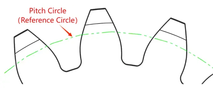
What These Circles Mean
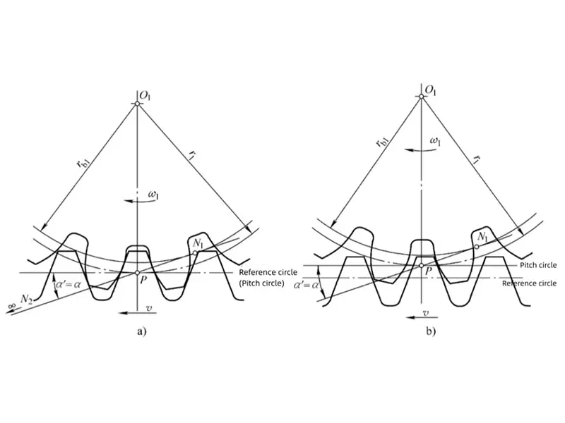
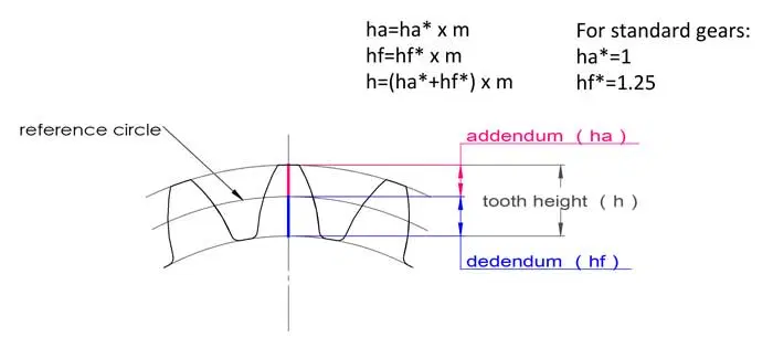
The reference circle is the fixed design circle defined by module and tooth count, while the pitch circle is the operating rolling circle that reflects the real meshing condition.See also: How to Calculate Gear Module
Why the Difference Matters
Design assumptions don’t match assembly reality
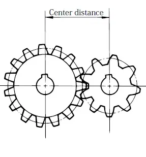
Standards assume a nominal center distance and ideal geometry, but real units see mounting tolerance, thermal growth, bearing clearance, and shaft deflection. As a result, the operating condition can drift even when each part looks “within tolerance” on its own.
Operating changes can shift contact behavior
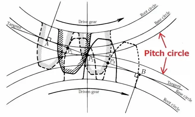
When the pitch circle differs from the reference circle, the operating pressure angle changes as well. That change can move the contact patch, alter sensitivity to transmission error, and change how backlash behaves under load—especially in noise-sensitive or high-speed applications.
It aligns design, manufacturing, and inspection
Once teams separate “reference geometry” from “operating geometry,” they can align expectations: what tooling and inspection should check, what center distance matters in assembly, and which deviations truly affect performance.
Typical Operating Scenarios
| Scenario | Reference circle | Pitch circle | What usually changes |
| Nominal center distance (standard installation) | Fixed by d = m × z | Matches reference circle | Operating pressure angle ≈ design pressure angle |
| Center distance increased (a’ > a) | Unchanged | Larger than reference circle | Operating pressure angle increases; backlash/contact may shift |
| Center distance decreased (a’ < a) | Unchanged | Smaller than reference circle | Operating pressure angle decreases; interference/edge contact risk may rise |
| Loaded/deflected assembly | Unchanged | Shifts with deflection and bearing clearances | Contact stability and TE/NVH sensitivity may change |
| Intentional design change (profile shift / modified geometry) | Still defined for the gear | Operating may differ by design intent | Performance targets may require different operating assumptions |
Practical takeaway: the reference circle stays constant for a given gear design, but the pitch circle represents how the pair actually rolls together once you account for center distance and real assembly behavior.
Who Uses This Distinction
- Gear design engineers defining geometry, tolerances, and center distance targets
- Manufacturing engineers setting tooling assumptions and process checks
- Quality teams performing tooth thickness, span, or measurement-over-pins checks
- NVH engineers analyzing transmission error and contact stability
- OEM and rebuild programs troubleshooting fit, backlash, noise, or temperature rise
- Sourcing teams writing RFQs and aligning acceptance criteria
Key Differences in Practice
| Item | Reference circle (design) | Pitch circle (operation) |
| Definition | Fixed circle used to define standard geometry | Operating rolling circle during meshing |
| Depends on | Module (m) and tooth count (z) | Actual center distance (a’), ratio, and operating state |
| Pressure angle | Design pressure angle (α) | Operating pressure angle (α’) |
| Main use | Tooling setup, geometry definition, inspection baselines | Performance analysis, meshing behavior, TE/NVH discussion |
| Fixed or variable | Fixed for a given gear | Can shift with assembly and load conditions |
| What it predicts well | Standard tooth thickness and spacing targets | Real contact behavior and sensitivity to deviation |
A helpful way to remember it: reference circle = what you build to, pitch circle = how it runs. That distinction becomes especially valuable when you diagnose noise, heat, or “good parts that don’t feel good” in an assembled unit.
Practical Benefits of Knowing Both
| Goal | Benefit | Why it helps |
| Clearer RFQs and drawings | Fewer misunderstandings around “pitch diameter” | Avoids quoting to the wrong assumption |
| Better tolerance decisions | Predict operating pressure angle drift | Reduces unexpected contact and NVH issues |
| Stronger inspection planning | Choose checks that match the question | Avoids measuring the right thing for the wrong reason |
| Faster troubleshooting | Separate design intent from operating reality | Shortens root-cause cycles for fit/backlash complaints |
| More stable performance | Align assembly center distance with design | Improves repeatability across production lots |
Supplier Selection Tips
- State which “pitch” you mean: clarify whether pitch diameter is a reference value (d = m × z) or an operating value tied to center distance.
- Provide nominal center distance and allowed variation: center distance tolerance often drives operating pressure angle and backlash behavior.
- Align inspection methods and acceptance evidence: specify reference-based checks (tooth thickness/span/over pins) and any functional checks tied to assembly datums.
- Share operating priorities (noise, heat, TE): provide speed/load ranges so the supplier can recommend practical controls.
- Define backlash the way you measure it in assembly: agree on measurement location and method so results remain comparable.
Why Choose Us
Wenlio Gear supports precision gear projects with a focus on geometric clarity and repeatable inspection evidence.
We help teams align reference-geometry requirements (module, tooth count, standard pressure angle assumptions) with operating-geometry realities such as center distance variation and assembly datums.
When projects require tighter performance control, we also support practical checks that reflect real behavior—such as runout alignment to functional datums and condition-based verification that improves meshing stability.
This approach helps reduce misunderstandings where a gear “passes inspection” but the assembly still shows unexpected backlash, noise, or contact sensitivity.
FAQ
Q1: Are reference circle and pitch circle always the same?
A: No. They coincide at nominal center distance in standard installation. With center distance changes or deflection, the operating pitch circle can differ.
Q2: What is the reference circle formula in module systems?
A: Reference diameter is d = m × z.
Q3: Why does center distance change operating pressure angle?
A: Center distance changes the operating geometry of the mesh, which shifts the effective rolling condition and therefore the operating pressure angle (α’).
Q4: Does load affect the pitch circle?
A: Load can introduce deflection and change contact conditions. While the reference circle stays fixed, the operating state may shift and change contact stability and TE sensitivity.
Q5: Which circle matters most for inspection?
A: Reference geometry dominates tooling and basic inspection. Operating pitch behavior matters more when you analyze performance issues such as backlash change, noise, or contact behavior.
Conclusion
Reference circle and pitch circle describe two different truths: the reference circle defines the standard geometry you design and manufacture, while the pitch circle describes how gears actually roll together in operation. When center distance shifts—due to tolerance, thermal growth, or deflection—the operating pitch circle and pressure angle can change, affecting contact behavior, backlash, and transmission quality.
If you are validating a gear design, diagnosing noise/backlash concerns, or preparing an RFQ that involves center-distance variation, you are welcome to Contact Us to share drawings and operating conditions so we can align design assumptions with real operating geometry.
Authoritative References
- Gear Technology – Measuring Pitch Diameter (pitch diameter as a reference dimension)
- Gear Solutions – Gear inspection basics (measurement over pins/balls context)
- NASA NTRS – Gear dynamics/contact research (center distance & pressure angle related)
As a gear engineer, I appreciate the clarification between the reference circle and the pitch circle. In theory they coincide for standard gears, but in real assemblies factors such as load, elastic deformation, and slight alignment variations can shift the actual meshing conditions. Understanding this distinction is important when troubleshooting noise, wear patterns, or contact issues in practical gear systems.
Good explanation of a concept that is often simplified in textbooks.