
Blogs, Bevel Gear
How Does a Bevel Gear Work? Types and Contact Pattern Basics
Mar
Introduction
How bevel gears work looks simple on paper—two gears turn power through a 90° corner. In real machines, the details decide everything: contact pattern under load, noise targets, housing constraints, and allowable center-distance variation. That is why bevel gear sets can behave very differently even when the ratio looks the same.
At Wenlio Gear, we support bevel and hypoid gear programs where stable meshing matters more than textbook geometry. This guide explains the working principle of bevel gears, how the major types differ in contact behavior, and how to think about selection and RFQ inputs in a way that reduces iteration.
One-line definition
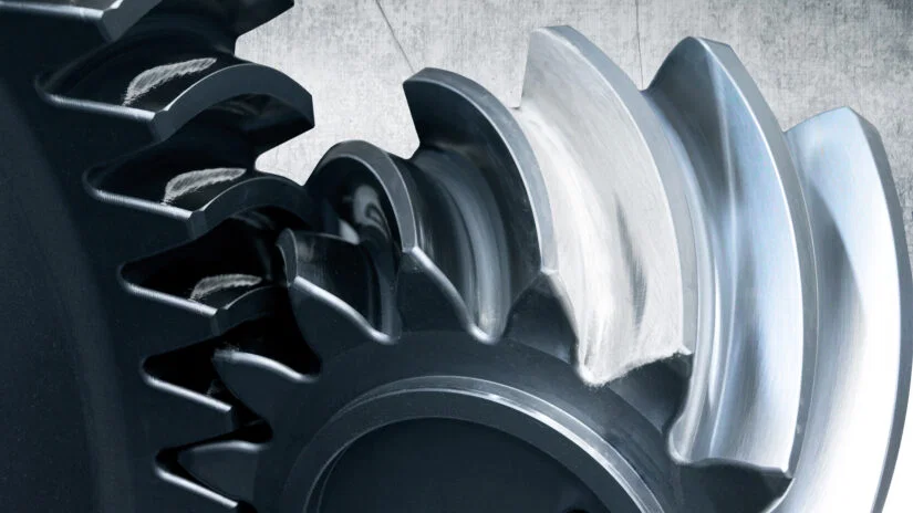
Bevel gears transmit torque between intersecting shafts by rolling contact on pitch cones, converting rotation direction and speed through the gear ratio.
Why the working principle matters
Bevel gears “turn power,” but they also shape system behavior
Because the mesh happens on conical tooth surfaces, small changes in setup or load can shift contact location and change noise or wear trends.
Contact pattern is not a “nice-to-have”
The same gear set can run cool and quiet with a centered pattern, or run hot and noisy with edge contact. Understanding the mechanism helps you predict where risk comes from.
Choosing the type sets your performance ceiling
Straight bevel can meet basic needs at lower cost, while spiral and hypoid better support higher load and lower NVH targets—if you control geometry and verification correctly.
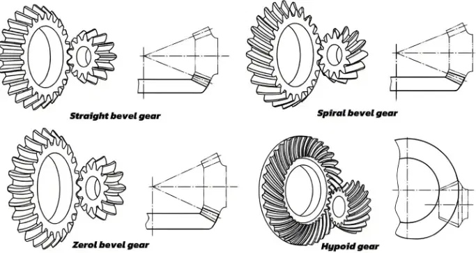
The main bevel gear families at a glance
.webp)
| Type | What changes in the mesh | Typical outcome | Best fit |
| Straight bevel | Abrupt local contact at engagement | Higher impact/noise at speed | Cost-sensitive, lower speed/load |
| Spiral bevel | Progressive engagement with overlap | Lower noise, smoother load transfer | Precision right-angle drives |
| Zerol bevel | Curved tooth surface with ~0 spiral angle | Middle ground: smoother than straight | Balanced cost + improved smoothness |
| Hypoid (offset) | Added sliding from shaft offset + surface contact growth | High load capacity, low noise potential | High torque + packaging offset needs |
Where bevel gears show up in real systems
- Right-angle drives in industrial machinery and automation modules
- Axle and differential-style power transfer stages (where applicable)
- Construction and off-highway final drive architectures (application dependent)
- EV drivetrain right-angle layouts and compact drive units (depending on design)
- Machine tools and precision motion systems that require stable alignment
What actually happens during meshing
| Step/Concept | What you see in operation | Why it matters |
| Pitch cones roll | Teeth transmit torque as pitch cones “roll” | Defines theoretical kinematics |
| Contact starts local | Initial contact begins as a small patch | Local stress + sensitivity to alignment |
| Contact pattern moves | Pattern travels across tooth width/profile through rotation | Indicates load distribution |
| Overlap changes stability | More overlap usually reduces impact | Improves smoothness/NVH potential |
| Sliding vs rolling | Sliding raises heat and scuffing risk | Drives lubrication/efficiency needs |
| Assembly effects | Center distance and alignment shift pattern | Turns “good gear” into “bad mesh” |
A practical translation: designers often focus on ratio and size first, but the mesh “quality” depends on pattern stability and controlled variation in assembly.
How the four types differ in contact behavior
| What you want | Best match | Why it helps |
| Lower impact and smoother engagement | Spiral bevel | Progressive mesh reduces shock |
| Higher load capacity in compact space | Hypoid (offset) | Larger effective contact + strong layout |
| Cost control with basic performance | Straight bevel | Simple geometry and lower process cost |
| A compromise between cost and smoothness | Zerol | Curved surface without full spiral geometry |
Important: the type gives you capability, but contact pattern control decides whether you actually achieve it.
Supplier selection tips for bevel/hypoid projects
- Define the real performance priorities: share speed, torque, duty cycle, and whether NVH or temperature rise is the main constraint.
- Specify assembly datums and center-distance assumptions: a bevel set can meet drawing dimensions and still run poorly if the datum scheme does not match assembly reality.
- Align on verification evidence, not only pass/fail: ask what the supplier can provide for profile/lead/pitch/runout, plus how they confirm a stable contact pattern.
- Clarify lubrication and surface durability expectations: sliding components (especially hypoid) need proper lubricant strategy; align on how you evaluate scuffing risk.
- Confirm repeatability from prototype to batch: ask how the supplier controls tool setup, heat treatment distortion (if applicable), and inspection method consistency across lots.
Why Choose Us
Wenlio Gear supports precision bevel and hypoid gear programs with a focus on geometry clarity and repeatable inspection evidence.
We help teams translate design intent into manufacturable parameters, then verify outcomes with structured measurements—especially tooth profile and lead behavior, runout stability, and condition-based checks that reflect real meshing quality.
We also emphasize early alignment on datums and assembly assumptions, because bevel performance depends on the relationship between gear geometry and how the set sits in the real structure. That approach helps customers reduce iteration and keep prototype results consistent with batch production behavior.
FAQ
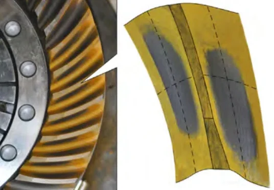
Q1: What is a contact pattern in bevel gears?
A: It is the real contact area between tooth surfaces during meshing. A centered, stable pattern usually indicates balanced load distribution.
Q2: Why are straight bevel gears louder than spiral bevel gears?
A: Straight bevel gears tend to engage with more abrupt local contact, creating higher impact. Spiral bevel gears engage progressively with overlap, reducing shock.
Q3: Does hypoid gearing always have lower efficiency?
A: Hypoid meshes add more sliding due to offset, so they often lose more energy as heat than spiral bevel, but real results depend on design, load, and lubrication.
Q4: What changes when center distance shifts?
A: The operating contact location and pressure angle can change, which shifts the pattern and can increase noise, heat, or edge contact risk.
Q5: What should I include in an RFQ for a bevel/hypoid set?
A: Ratio, speed/torque range, duty cycle, assembly datums/center distance, lubrication method, NVH/temperature targets, and required inspection evidence.
Conclusion
Bevel gears work by rolling contact on pitch cones to transmit torque between intersecting shafts, but real performance depends on how contact develops under load. Straight, spiral, Zerol, and hypoid sets share the same basic mechanism, yet they differ in how smoothly they engage, how much sliding they generate, and how sensitive they are to alignment and lubrication.
If you are selecting a bevel or hypoid gear set for a right-angle drive and want to reduce noise, heat, and iteration risk, you are welcome to Contact Us with your drawings and operating conditions so we can review the mesh assumptions and propose a practical verification plan.