
Blogs, Bevel Gear
How Curved Teeth Affect Spiral Bevel Gear Performance
Jul
Introduction
The curved tooth line is the most recognizable feature of a spiral bevel gear, but it is more than a visual difference. It changes how contact develops across the tooth surface, how neighboring teeth share load, and how forces are transferred into shafts and bearings.
At Wenlio, spiral bevel gear projects are reviewed as complete gear-pair systems rather than isolated parts. Speed, torque, shaft angle, mounting distance, spiral hand, bearing arrangement, accuracy, and inspection requirements must be considered together. This system-level review helps avoid selecting a tooth form that appears suitable on paper but conflicts with the existing housing, bearings, or mating gear.
Quick Answer: How Do Curved Teeth Affect Spiral Bevel Gears?
Curved spiral bevel gear teeth allow engagement to develop progressively across the tooth surface. In a properly designed and installed pair, this creates more continuous load sharing. It can also provide smoother torque transfer than a comparable straight bevel gear pair.
However, curved teeth also generate axial thrust. They are more sensitive to tooth geometry, mounting position, contact pattern, manufacturing accuracy, and bearing support. They can improve meshing behavior, but they do not guarantee lower noise or higher capacity in every application.
How Do Curved Teeth Affect Meshing and Load?
Progressive Engagement Across the Tooth Surface
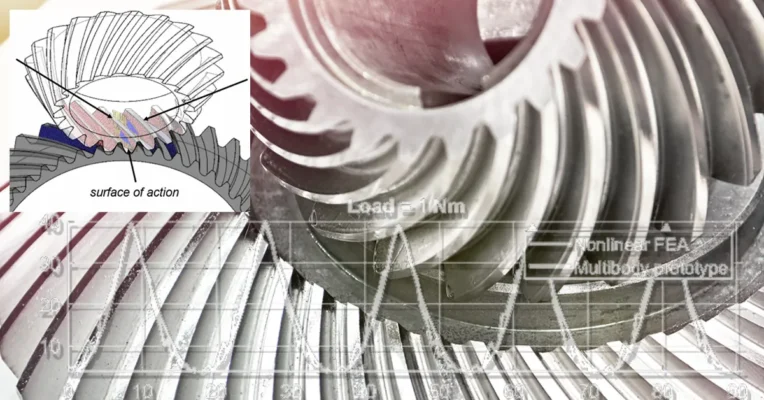
The teeth of straight bevel gears and spiral bevel gears enter mesh differently. Straight bevel teeth engage more directly, while curved spiral teeth allow contact to begin in one area, spread across the tooth surface, and leave mesh gradually.
Progressive entry can reduce impact as a new tooth pair begins carrying load. It can also make torque transfer more continuous. The benefit still depends on correct tooth geometry and installation. An inaccurate surface or mounting position can still cause noise, heat, vibration, or edge contact. The contact path must remain within the usable tooth area under load. Otherwise, expected smoothness may be lost, even if the gears rotate freely during a hand check.
Contact Ratio and Load Sharing
A properly designed spiral bevel gear set can achieve a higher total contact ratio than a similar straight bevel pair, allowing adjacent tooth pairs to share load during part of the meshing cycle.
Actual load distribution still depends on tooth modification, accuracy, contact position, mounting distance, housing stiffness, bearings, speed, torque, and shock loading. Curved teeth do not automatically increase capacity.
Noise and Running Smoothness
Curved teeth do not make every spiral bevel gear quiet. Progressive engagement may reduce sudden tooth entry, but noise also depends on pitch and tooth-surface deviations, surface finish, backlash, contact pattern, pair matching, housing rigidity, bearings, speed, and load variation.
If contact is concentrated near a tooth edge or the installed position differs from the design position, the gear pair may still run loudly even when individual dimensions appear acceptable.
How Do Curved Teeth Affect Forces and Installation?
Axial Thrust and Bearing Arrangement
When torque is transmitted, the normal force acting on the inclined spiral tooth surface can be resolved into tangential, radial, and axial components. The axial component changes with spiral hand, direction of rotation, spiral angle, pressure angle, and transmitted torque.
The bearing arrangement must therefore support the expected thrust and control shaft movement. Bearing type, preload, housing stiffness, and allowable displacement should be reviewed with the gear pair, not after the gears have already been manufactured. Uncontrolled shaft movement can shift the contact pattern during operation, so bearing support is part of the meshing condition rather than a separate mechanical detail.
Mounting Distance and Contact Pattern
Spiral bevel gears are sensitive to mounting position because small axial or positional changes can move the bevel gear contact pattern toward the heel, toe, tooth top, tooth root, or edge.
A shifted pattern reduces the effective contact area and may increase local pressure, noise, heat, or wear. Contact should be checked together with the specified mounting distance and bevel gear backlash, because clearance measured in another assembly position may not represent the final transmission.
Gear-Pair Matching and Spiral Hand
The mating members must have the correct spiral hands, orientation, shaft angle, and pairing relationship. Tooth count and ratio alone are not enough to prove compatibility.
Some projects require the pinion and gear to be manufactured, marked, or verified as matched bevel gear sets. For replacement work, both gears and their installed relationship should be reviewed when the remaining mating gear is worn, modified, or of an unknown revision.
What Do Curved Teeth Require in Manufacturing?
Tooth-Surface Geometry and Accuracy
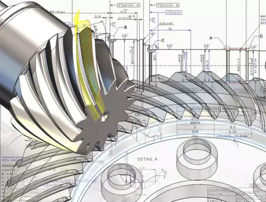
A spiral bevel tooth surface is a complex three-dimensional geometry. It cannot be fully defined by tooth count, module, and ratio alone. Depending on the gear system, manufacturing may also require nominal tooth-surface data, spiral angle and hand, pressure angle, shaft angle, mounting distance, mating-gear data, accuracy grade, backlash, and contact requirements.
A part may look similar to a worn sample and still fail to reproduce the intended meshing condition. Worn teeth should therefore be treated as reference evidence rather than perfect design data.
Inspection and Prototype Validation
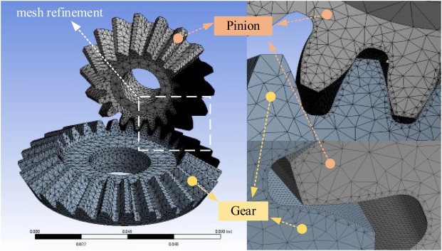
Inspection should match the gear pair’s function. It may include critical dimensions, tooth-surface results, pitch, runout, hardness, contact pattern, backlash at a defined position, pair marking, or a roll test.
Prototype approval criteria should be agreed before manufacturing so contact, assembly, and mating compatibility are evaluated as well as dimensions. For critical applications, the approval plan should also state the measuring position, mating member, lubricant condition, and whether acceptance is based on a static contact check or a rolling test.
Do Curved Teeth Always Improve Bevel Gear Performance?
When Spiral Bevel Gears Are Advantageous
Spiral bevel gears are often suitable when a right-angle transmission needs progressive engagement, smoother torque transfer, or more controlled tooth contact. These advantages are conditional: material, heat treatment, finishing, lubrication, accuracy, housing rigidity, bearings, and assembly all influence the result.
Why Straight and Spiral Bevel Gears Are Not Direct Substitutes
An existing straight bevel gear design should not be converted to spiral bevel gears solely to obtain smoother running. The change can affect the mating gear, axial bearing loads, mounting references, housing space, contact pattern, and inspection method.
Direct substitution is especially unsuitable when the original mating gear must remain in service, the bearings cannot support additional thrust, the housing cannot be changed, or complete gear-pair data is unavailable. In these cases, the complete transmission should be reviewed before changing the tooth form.
What Should Buyers Confirm Before Ordering Spiral Bevel Gears?
| Item | Information to Confirm |
| Gear type | Spiral bevel, straight bevel, Zerol, or hypoid. |
| Gear-pair data | Tooth counts, ratio, spiral hands, orientation, and matching marks. |
| Installation | Shaft angle, mounting distance, shaft position, bearings, and available space. |
| Operating conditions | Speed, torque, duty cycle, shock load, rotation direction, and lubrication. |
| Accuracy and contact | Standard, accuracy grade, backlash, contact pattern, and inspection scope. |
| Project documents | Drawings, 3D models, both old parts, installation data, or clear photographs. |
Tooth count and outside diameter alone are not enough to confirm correct meshing. Buyers should also state whether the project is a new design, a replacement set, or a single-part reproduction, as each requires different mating and installation data.
How Wenlio Reviews a Spiral Bevel Gear Project
For drawing-based or sample-based custom gear projects, Wenlio first confirms the gear type, ratio, shaft angle, mating relationship, spiral hand, mounting data, speed, torque, rotation direction, duty cycle, and bearing arrangement. Missing information is identified before the manufacturing route is finalized.
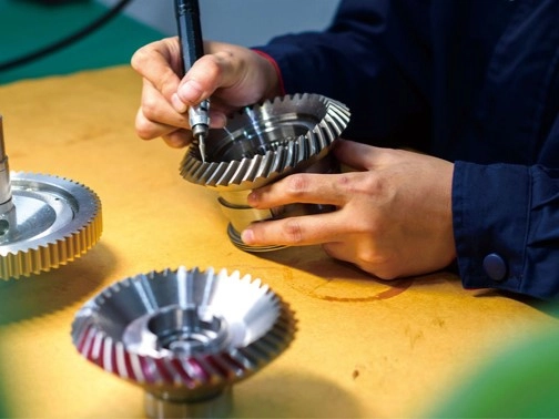
The next step is to define what the prototype or first article must prove. Depending on the project, this may include critical dimensions, tooth inspection, hardness records, backlash, contact pattern, pair marking, or assembly feedback. Replacement projects without complete drawings may require both gears and their installed relationship to be reviewed.
FAQ
Why Do Spiral Bevel Gears Use Curved Teeth?
Curved teeth create progressive engagement and can support smoother load sharing when the gear pair is correctly designed and installed.
Do Curved Teeth Always Increase Load Capacity?
No. Capacity also depends on size, material, heat treatment, geometry, accuracy, lubrication, and operating conditions.
Are Spiral Bevel Gears Always Quieter?
Not always. Noise also depends on accuracy, finish, backlash, contact pattern, bearings, housing stiffness, speed, and load.
Why Must the Spiral Hand Be Confirmed?
The mating gears need the correct spiral hands, orientation, and pairing relationship; tooth count and ratio alone are insufficient.
Can Spiral Bevel Gears Replace Straight Bevel Gears?
Usually not. The gear pair, mounting positions, axial thrust, bearings, housing, contact pattern, and manufacturing data require review.
Conclusion
Curved teeth affect how spiral bevel gears enter mesh, share load, and transmit force, influencing operating smoothness, axial thrust, manufacturing accuracy, and installation requirements. Buyers should evaluate the complete gear pair, including gear type, mating relationship, shaft angle, mounting distance, spiral hand, speed, torque, and bearing conditions.
For a spiral bevel gear project review, Contact Us to send drawings or photos of both gears, ratio, shaft angle, installation dimensions, and operating conditions. This information helps determine a suitable gear-pair solution.
